
|
drive.web
savvy-SFD
SFD Menu
|
The SFD Menu controls top-level functions of the graphical interface to your drive.web configuration.
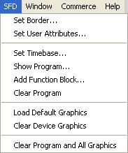
Clear Program and All Graphics
When selected, a secondary window appears giving you control of the appearance of your SFD drawing.
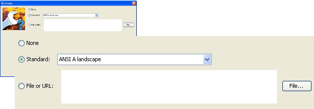
Selects no border. The page is practically limitless.
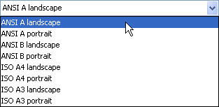
Selects your desired American National Standards Institute (ANSI) or International Organization for Standardization (ISO) standard page sizes as follows:
|
11 x 8.5 inches | (279 x 216 mm) |
|
8.5 x 11 inches | (216 x 279 mm) |
|
17 x 11 inches | (432 x 279 mm) |
|
11 x 17 inches | (279 x 432 mm) |
|
297 x 210 mm | (11.7 x 8.3 inches) |
|
210 x 297 mm | (8.3 x 11.7 inches) |
|
420 x 297 mm | (16.5 x 11.7 inches) |
|
297 x 420 mm | (11.7 x 16.5 inches) |
Selects a custom border, the appropriate file may be selected using the File... button.
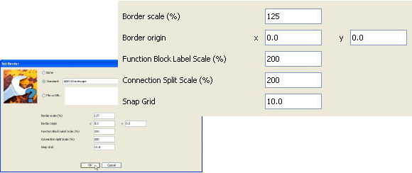
Scales the page by changing the border's zoom factor. A larger scale will allow more function blocks per page while a smaller scale will result in fewer function blocks per page.
The border can be shifted using the x and y data fields. The origin is the upper left-hand corner of the graphic. The x and y coordinates are in pixels.
Sets the size of the text labeling the function blocks in you drawing in the range from 50% to 300%.
Sets the size of the text labeling of split connections in you drawing in the range from 50% to 300%.
Sets the snap grid (in pixels) for your SFD drawing in the range from 0 to 65535.
Sets the information to be displayed in the title block of the border. When selected, a secondary window with fields that match the labeling of the title block is displayed.
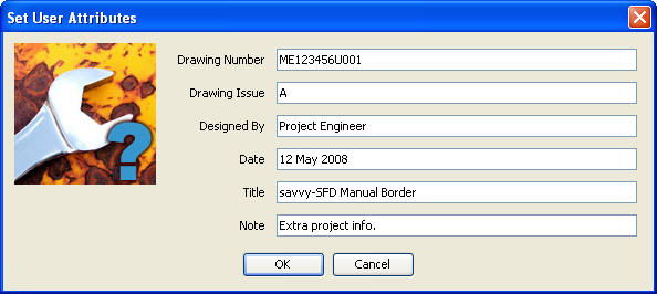
The resulting title block will appear as follows:

The device name (in this case speedy-sp), current page number, and total number of pages are automatically updated in the title block as they change. The User Attributes appear on every page of the SFD configuration.
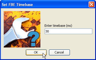
Sets the Function Block Engine (FBE) Timebase Setpoint for the of drive.web device. Effectively, the cycle time desired for the configuration which includes the execute time of the program and any overhead functions.
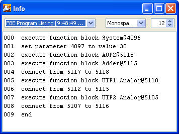
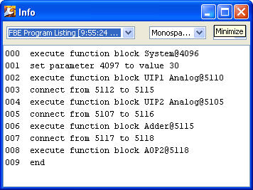
Generates a text listing of the FBE program in the execution order with line numbers.
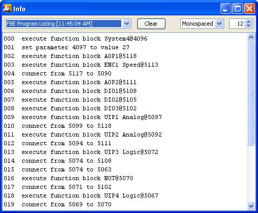
The FBE Program text listing has two very useful functions:
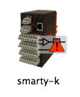
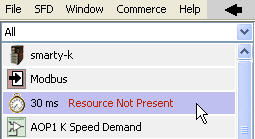
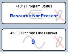
If there is a FBE Program problem (as indicated by the warning adornment below), click on the device. Then, click on the System block (the clock icon).
 |
 |
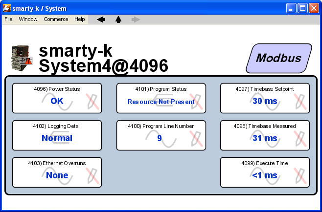 |
Inside the System block, the Program Line Number will identify the line number and associated function block or connection which is causing the problem.
In general, as function blocks are added to a drive.web Function Block Engine configuration, the new blocks are added to the end of the program. Normally, this scheme for adding function blocks has no adverse effect on performance. However, if you really need to optimize execution perfomance, the function blocks can be re-ordered using the FBE Viewer window.
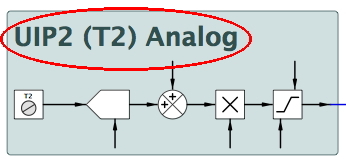
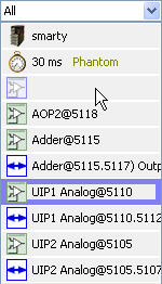
When viewing a program in the Diagram Viewer, the executiom order is not obvious. Consider the following program:
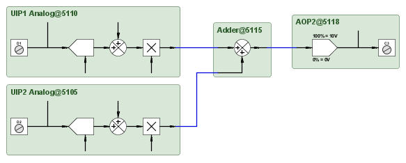
Using the the Show Program... command, one can see the order in which the function blocks were created top to bottom. In this case, Analog Output 2 (AOP2) was the first user function block created while Universal Input 2 (UIP2) was the last block created. The associated FBE Viewer is shown to the right.
 |
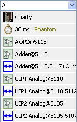 |
To change the execution order, in the FBE Viewer simply drag the block you wish to relocate to the desired position in the list. Moving the function block will ensure its output(s) are updated prior to execution of function blocks later in the FBE Viewer listing.
Again, using the the Show Program... command, one can verify the program's execution order has been optimized in the program listing and the FBE Viewer.
 |
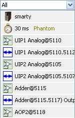 |
With these changes to the order of the function blocks, the execution path will be optimized.
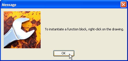
When selected, a dialog box appears telling the user how to place a function block on the SFD drawing page.
Clears the FBE program (not device level program/parameters) in the device, but leaves the graphical data such as the borders.
Loads the default graphics for the device.
Clears the graphical data from the SFD drawing, but leaves the function blocks in the module as evident by the FBE Viewer listing.
Clears both the FBE program (not device level program/parameters) and all the graphical data effectively purging the module of all configuration data.