|
Motion Control
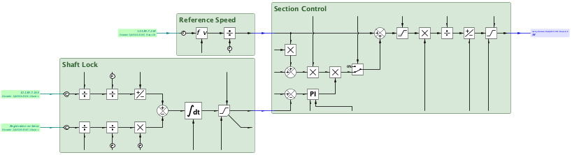
Shaft Lock v1
|
| Description | Shaft Lock
|
| Availability |
|
| savvy-SFD Graphic |  |
| Graphic with Parameters | 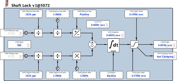 |
| Reference Input |
Input, Read-only, Placeholder (special (count & timestamp)) Reference Input
|
| Follower Input |
Input, Read-only, Placeholder (special (count & timestamp)) Follower Input
|
| Reference Pulses/Rev |
Input, Read-write, Analog (signed 16-bit integer) 1 ppr to 30000 ppr |
| Follower Pulses/Rev |
Input, Read-write, Analog (signed 16-bit integer) 1 ppr to 30000 ppr |
| Reference Gear Ratio |
Input, Read-write, Analog (32-bit IEEE-754 floating point value) -340E36 to 340E36 |
| Follower Gear Ratio |
Input, Read-write, Analog (32-bit IEEE-754 floating point value) -340E36 to 340E36 |
| Reference Sign |
Input, Read-write, Boolean (signed 16-bit integer) 0 = Positive 1 = Negative |
| Follower Ratio |
Input, Read-write, Analog (32-bit IEEE-754 floating point value) -340E36 to 340E36 |
| Reset |
Input, Read-write, Boolean (signed 16-bit integer) Reset
0 = Inactive 1 = Reset |
| Upper Clamp |
Input, Read-write, Analog (signed 16-bit integer) 0.0000 revs to 3.2767 revs If the Input exceeds this value, the Output will be set to this value. |
| Lower Clamp |
Input, Read-write, Analog (signed 16-bit integer) -3.2767 revs to 0.0000 revs If the Input is less than this value, the Output will be set to this value. |
| Output |
Output, Read-only, Analog (signed 16-bit integer) -3.2767 revs to 3.2767 revs Output
-32767 = - overrange 32767 = + overrange |
| Clamping Output |
Output, Read-only, Boolean (signed 16-bit integer) 0 = Not Clamping 1 = Clamping |
| Status |
Internal Parameter, Read-only, Enumerated (signed 16-bit integer) Status
0 = OK 1 = Ref Fault 2 = Flw Fault 3 = Ref & Flw Fault |
| Error |
Internal Parameter, Read-only, Analog (signed 16-bit integer) -3.2767 revs to 3.2767 revs Status
-32767 = - overrange 32767 = + overrange |