|
Logic
State Machine 16-16
|
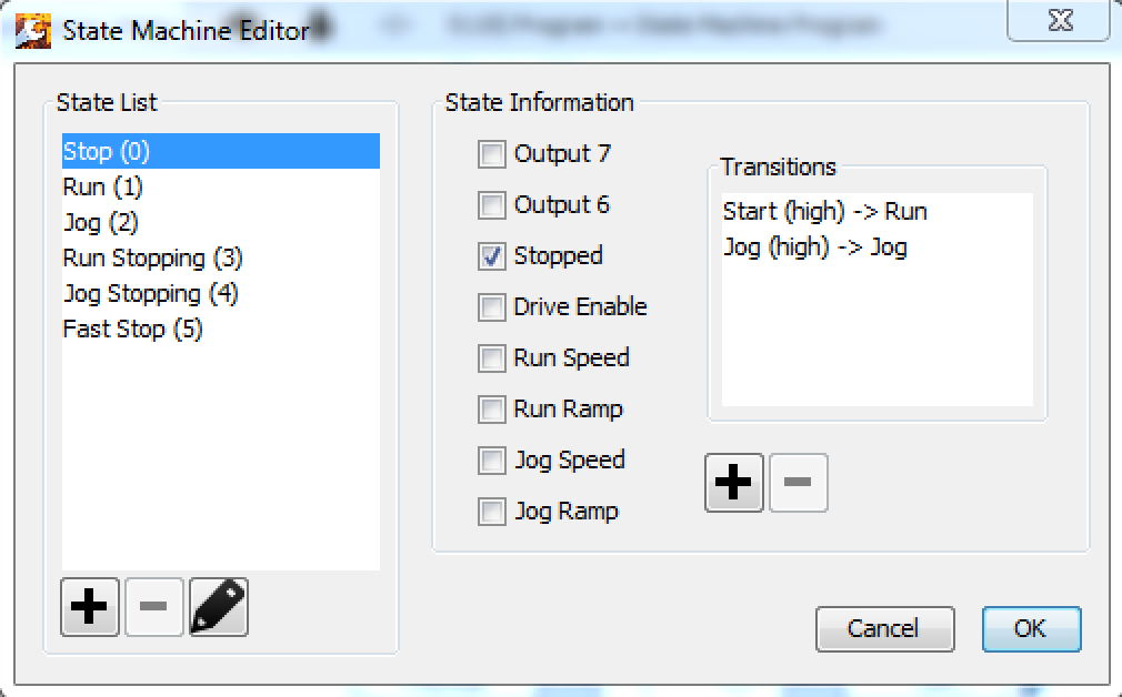
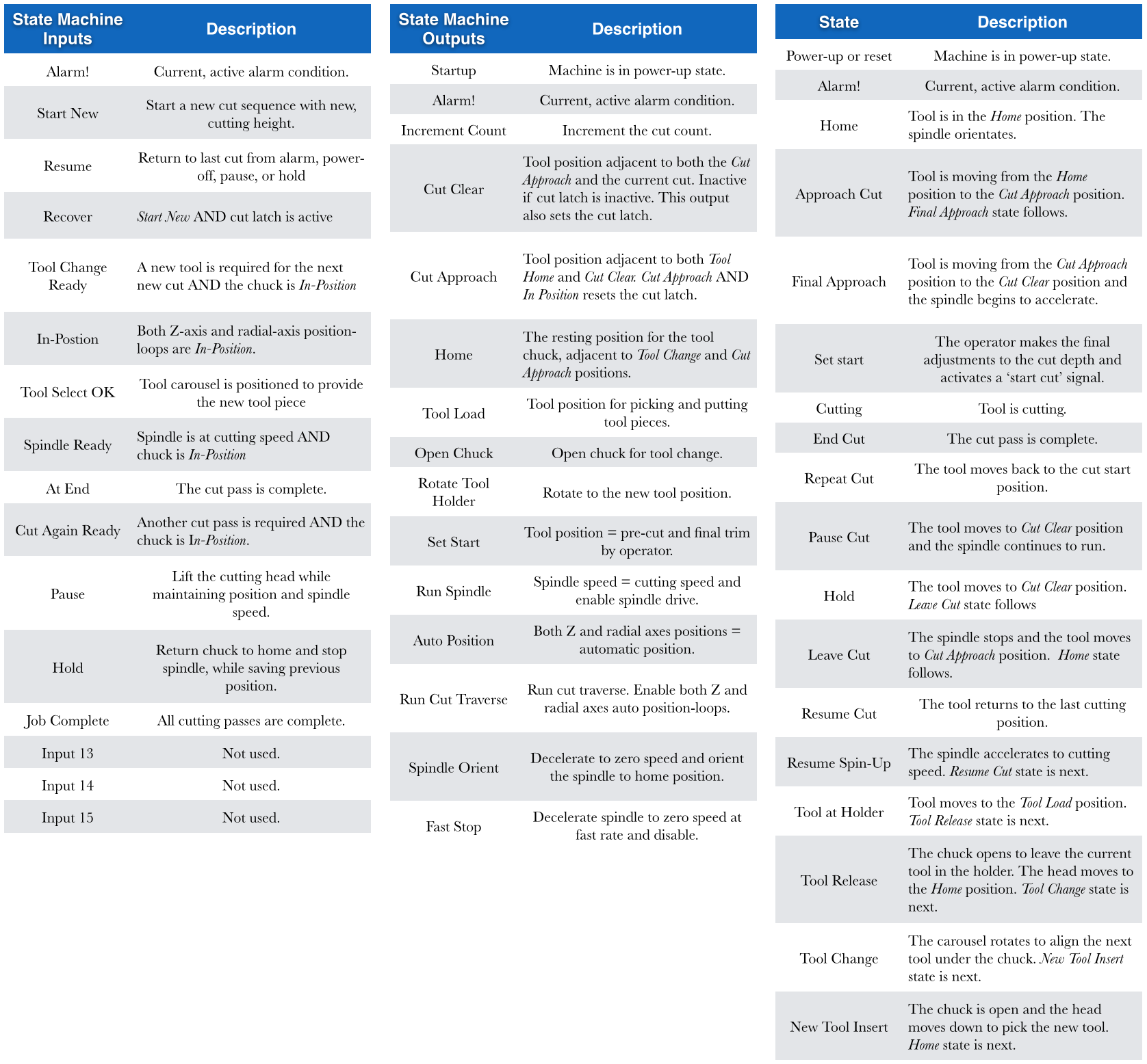
| Description | State Machine A Moore finite state machine. The function block outputs are defined only by the current state, and not the inputs. State transitions are controlled only by particular inputs for any given state.
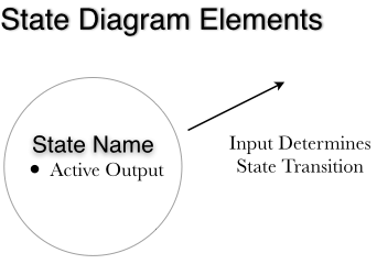
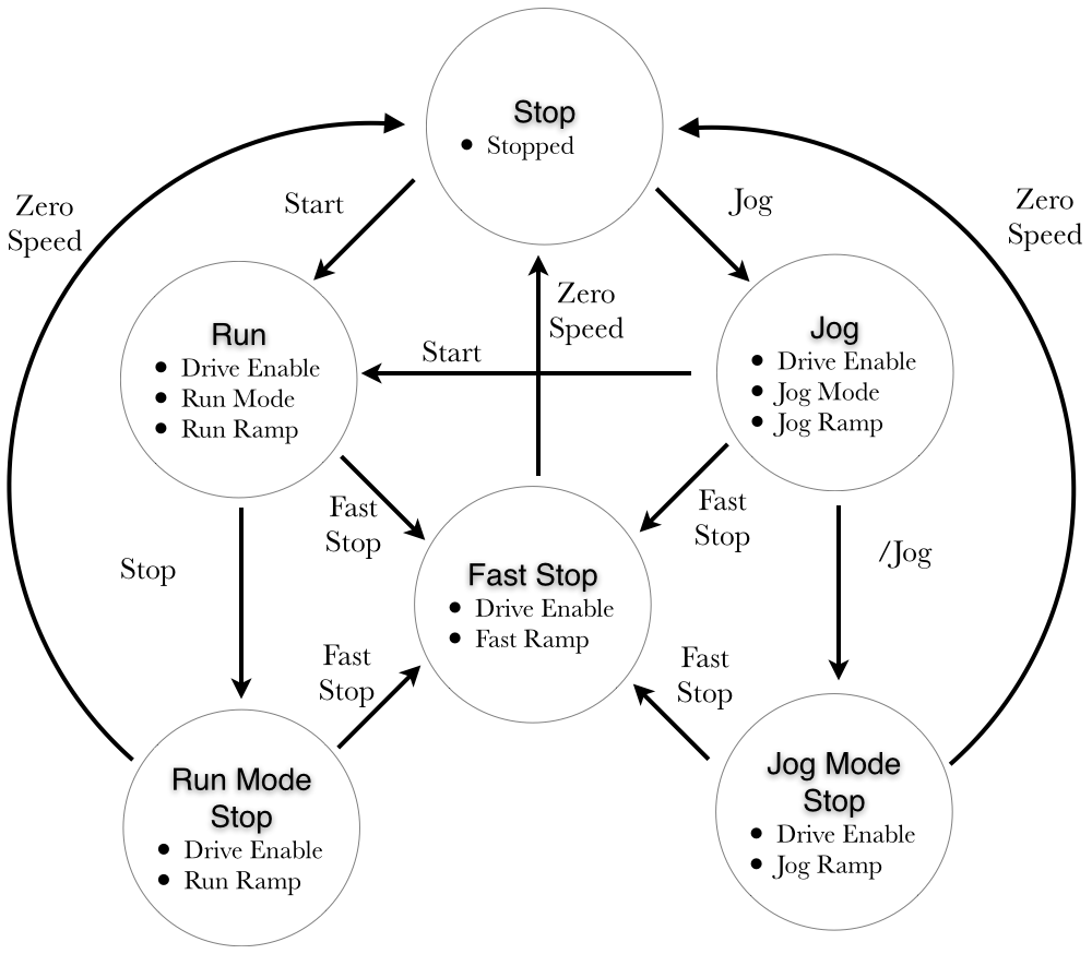
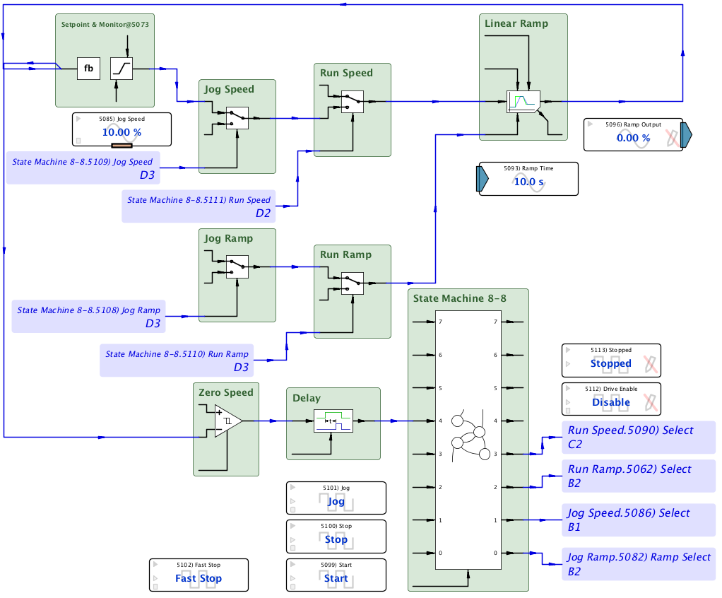
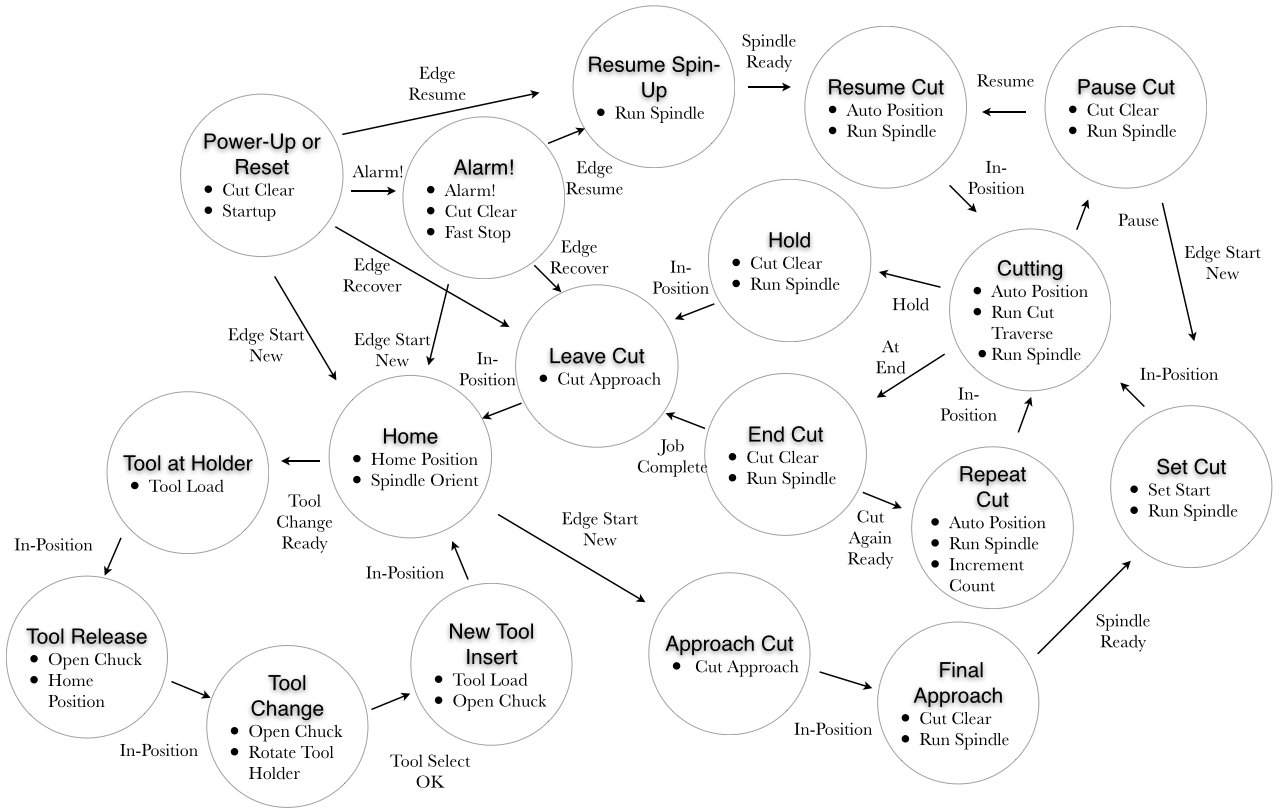
Application Example - Basic Ramp Control State Machine handles stop, start, fast-stop, jog, and their ramp times in a Linear Ramp function block. Program Design Technique It is helpful to draw a state diagram of the program design. Circles represent discrete states and list the output(s) for that state. Arrows connect states and are represented with arrows along with the discrete input(s) that cause the transition.
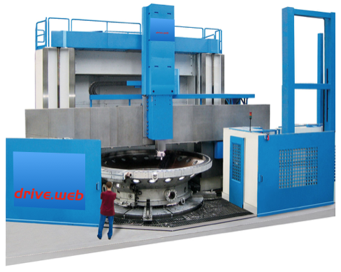
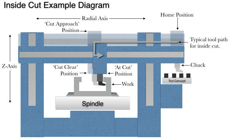
Application Example - Vertical Lathe
|
| Availability |
|
| savvy-SFD Graphic | 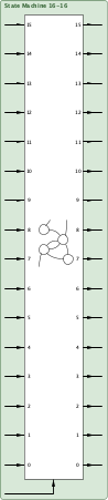 |
| Graphic with Parameters | 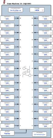 |
| Input 0 |
Input, Read-write, Boolean (signed 16-bit integer) 0 = Low 1 = High |
| Input 1 |
Input, Read-write, Boolean (signed 16-bit integer) 0 = Low 1 = High |
| Input 2 |
Input, Read-write, Boolean (signed 16-bit integer) 0 = Low 1 = High |
| Input 3 |
Input, Read-write, Boolean (signed 16-bit integer) 0 = Low 1 = High |
| Input 4 |
Input, Read-write, Boolean (signed 16-bit integer) 0 = Low 1 = High |
| Input 5 |
Input, Read-write, Boolean (signed 16-bit integer) 0 = Low 1 = High |
| Input 6 |
Input, Read-write, Boolean (signed 16-bit integer) 0 = Low 1 = High |
| Input 7 |
Input, Read-write, Boolean (signed 16-bit integer) 0 = Low 1 = High |
| Input 8 |
Input, Read-write, Boolean (signed 16-bit integer) 0 = Low 1 = High |
| Input 9 |
Input, Read-write, Boolean (signed 16-bit integer) 0 = Low 1 = High |
| Input 10 |
Input, Read-write, Boolean (signed 16-bit integer) 0 = Low 1 = High |
| Input 11 |
Input, Read-write, Boolean (signed 16-bit integer) 0 = Low 1 = High |
| Input 12 |
Input, Read-write, Boolean (signed 16-bit integer) 0 = Low 1 = High |
| Input 13 |
Input, Read-write, Boolean (signed 16-bit integer) 0 = Low 1 = High |
| Input 14 |
Input, Read-write, Boolean (signed 16-bit integer) 0 = Low 1 = High |
| Input 15 |
Input, Read-write, Boolean (signed 16-bit integer) 0 = Low 1 = High |
| Reset |
Input, Read-write, Boolean (signed 16-bit integer) 0 = Inactive 1 = Reset |
| Output 0 |
Output, Read-only, Boolean (signed 16-bit integer) 0 = Low 1 = High |
| Output 1 |
Output, Read-only, Boolean (signed 16-bit integer) 0 = Low 1 = High |
| Output 2 |
Output, Read-only, Boolean (signed 16-bit integer) 0 = Low 1 = High |
| Output 3 |
Output, Read-only, Boolean (signed 16-bit integer) 0 = Low 1 = High |
| Output 4 |
Output, Read-only, Boolean (signed 16-bit integer) 0 = Low 1 = High |
| Output 5 |
Output, Read-only, Boolean (signed 16-bit integer) 0 = Low 1 = High |
| Output 6 |
Output, Read-only, Boolean (signed 16-bit integer) 0 = Low 1 = High |
| Output 7 |
Output, Read-only, Boolean (signed 16-bit integer) 0 = Low 1 = High |
| Output 8 |
Output, Read-only, Boolean (signed 16-bit integer) 0 = Low 1 = High |
| Output 9 |
Output, Read-only, Boolean (signed 16-bit integer) 0 = Low 1 = High |
| Output 10 |
Output, Read-only, Boolean (signed 16-bit integer) 0 = Low 1 = High |
| Output 11 |
Output, Read-only, Boolean (signed 16-bit integer) 0 = Low 1 = High |
| Output 12 |
Output, Read-only, Boolean (signed 16-bit integer) 0 = Low 1 = High |
| Output 13 |
Output, Read-only, Boolean (signed 16-bit integer) 0 = Low 1 = High |
| Output 14 |
Output, Read-only, Boolean (signed 16-bit integer) 0 = Low 1 = High |
| Output 15 |
Output, Read-only, Boolean (signed 16-bit integer) 0 = Low 1 = High |
| State Persistence |
Internal Parameter, Read-write, Boolean (signed 16-bit integer) 0 = Zero on power-up 1 = Persistent |
| State |
Internal Parameter, Read-only, Enumerated (signed 16-bit integer) 0 = Initial |
| Program |
Internal Parameter, Read-write, State Machine Program (Byte Array) |