
|
ModbusRTU Master
Modbus Data INT16
|
| Description | When the data obtained from the slave device is an unsigned 16-bit integer (Range = 0 to 65535), the Modbus Data INT16 should be used. |
| Availability |
|
| savvy-SFD Graphic | 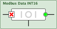 |
| Graphic with Parameters | 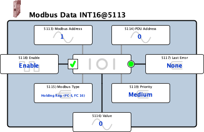 |
| Modbus Address |
Internal Parameter, Read-write, Analog (signed 16-bit integer) 1 to 247 The Modbus RTU address of the slave device on the EIA-485 network. |
||||||||
| PDU Address |
Internal Parameter, Read-write, Analog (unsigned 16-bit integer) 0 to 65000 The register's offset (wire) address of the data in the slave device. Typically, one less than specified Modbus RTU Address (e.g., to poll the data at Holding Register 40108 set the Data Address to 107). Please refer to the Modbus Documentation for more information. |
||||||||
| Modbus Type |
Internal Parameter, Read-write, Enumerated (signed 16-bit integer) The Modbus RTU function code to be used to communicate wThe Modbus RTU function code to be used to communicate with the slave device. Supported Function Codes are:
Note: Supported Function Codes are:
0 = Holding Reg. (FC 3, FC 16) 1 = Holding Reg. (FC 3, FC 6) 2 = Holding Reg. (Yaskawa) 3 = Input Reg. (FC 4) 4 = Coil (FC 1, FC 5) 5 = Input Discrete (FC 2) |
||||||||
| Value |
Input, Read-write, Analog (signed 16-bit integer) -32767 to 32767 The data that was either read from, or is to be written to, the associated register in the slave device. The Re-Name and Re-Scale contextual menu items can be use to make the raw data more meaningful in savvy. |
||||||||
| Last Error |
Output, Read-write, Enumerated (signed 16-bit integer) The result of the last poll of the associated register address in the slave. If an error occurs, the local Last Error code may be cleared by clicking on this parameter and using the Reset command. -16 = Unexpected Response -15 = Multiple Errors (parity, framing, overrun, or break) -14 = Break Received -13 = Overrun Error -12 = Framing Error -11 = Parity Error -10 = Unknown Error -9 = Unexpected Byte Count -8 = Unexpected Length -7 = Internal Error -6 = Unexpected Function Code -5 = CRC Failure -4 = Unexpected Address -3 = Runt Response -2 = Timeout -1 = No Comms Port Defined 0 = None 1 = Illegal Function 2 = Illegal Data Address 3 = Illegal Data Value 4 = Slave Device Failure 5 = Acknowledge 6 = Slave Device Busy 7 = Negative Acknowledge 8 = Memory Parity Error 33 = Data Out of Range 34 = Write Protected 35 = Write during Undervoltage 36 = Write during Parameter Processing |
||||||||
| Enable |
Input, Read-write, Boolean (signed 16-bit integer) Used to Enable/Disable the polling of the associated register address in the slave. 0 = Disable 1 = Enable |
||||||||
| Priority |
Internal Parameter, Read-write, Enumerated (signed 16-bit integer) This parameter determines how often the associated parameter is updated on the Modbus RTU comms link. Generally, the round-robin polling scheduler prioritizes the parameters as follows:
For example, for two High parameters (H1, H2), three Medium parameters (M1, M2, M3), and two Low parameters (L1, L2) the sequence would be. H1, H2, M1, H1, H2, M2, H1, H2, M3, H1, H2, L1, 0 = Low 1 = Medium 2 = High |