|
Ramps
Master Ramp
|
| Description | Master Ramp Function Block TopicsGeneralPurposeFeatures Inputs Outputs Modes of OperationRun ModeRun Mode Trend Slow Mode Slow Mode Trend Jog Mode Jog Mode Trend Miscellaneous PurposeThe Master Ramp function block is used to provide a coordinated reference to a number of devices using the drive.web technology. Although generally used with motion control applications, it may be used on any devices where a coordinated signal is required. For motion control applications, the Master Ramp usually provides the global speed reference to a number of motor controllers. From this global reference, a local control loop will modify the reference to meet the requirements of the section's process (e.g., on web handling equipment the global speed reference will be summed with the trim of a PI Loop to maintain constant tension). FeaturesSome highlights of the Master Ramp are listed below:
Master Ramp InputsThe following is a list of the Control Inputs available for direct connection at the savvy-SFD level:
Master Ramp OutputsThe following is a list of the Control Outputs available for direct connection at the savvy-SFD level:
Modes of OperationTo illustrate the behavior of the Master Ramp, a complete cycle for each of the Running Modes is detailed in the following sections (with all the associated steps). Each mode's cycle begins in the stopped condition, moves through each of the steps of the applicable mode sequentially, and then returns to the stopped condition with no transitions to any of the other Running Modes along the way. Run ModeThe basic sequence of events for Running Mode follows: StoppedThe idle state of the ramp. The Ramp Output is zero and the Run Output is Inactive.Run DelayUpon entering Running Mode (by asserting the Master Run), the user settable Run Delay timer begins timing while the Ramp Output is held at zero.RunningOnce the Run Delay timer has expired, the Ramp Output is released and will ramp up to the Ramp Input value using the Forward Up Time (or Reverse Up Time if the Ramp Input is negative).StoppingThe stopping mode varies depending on which stop input becomes active. All of the stops will cause the Master Ramp to exit Running Mode; however, only Stop allows the user to return to either Running Mode or Slow Running Mode by re-asserting either the Master Run or Master Slow input, respectively.When the Stop is active (Low) (used for normal operation), the Ramp Input will be set to zero and the ramp moves towards zero speed using the Stop Ramp Time/S Percent. When the output falls below the At Zero Speed Tolerance, the Drop Out Delay begins. Dropping OutThe Ramp Output is held at zero speed for the duration of the Drop Out Delay. If the Drop Out Delay timer expires, the ramp returns to the normal Stopped state. If any of the run inputs are re-asserted while the timer is still timing, the ramp will re-initiate the appropriate delay for the selected mode (just as if starting from the Stopped state).Run Mode Trend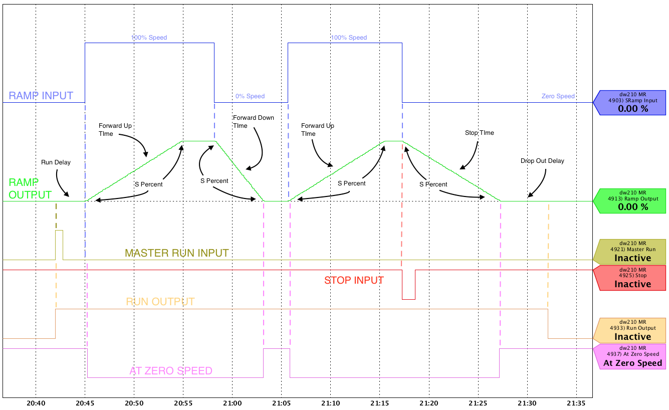 Slow ModeThe basic sequence of events for Slow Running Mode follows: StoppedThe idle state of the ramp. The Ramp Output is zero and the Run Output is Inactive.Slow DelayUpon entering Slow Running Mode (by asserting Master Slow), the user settable Slow Delay timer begins timing while the Ramp Output is held at zero.Slow RunningOnce the Slow Delay timer has expired, the Ramp Output is released and will ramp up to the Slow Speed using the Forward Up Time (or Reverse Up Time if the Slow Speed is negative).StoppingThe stopping mode varies depending on which stop input becomes active. All of the stops will cause the Master Ramp to exit Slow Running Mode; however, only Stop allows the user to return to either Running Mode or Slow Running Mode by re-asserting either the Master Run or Master Slow input, respectively.When the Stop is active (Low) (used for normal operation),the Ramp Input will be set to zero and the ramp moves towards zerospeed using the Stop Ramp Time/S Percent. When the output fallsbelow the At Zero Speed Tolerance, the Drop Out Delaybegins. Dropping OutThe Ramp Output is held at zero speed for the duration of the Drop Out Delay. If the Drop Out Delay timer expires, the ramp returns to the normal Stopped state. If any of the run inputs are re-asserted while the timer is still timing, the ramp will re-initiate the appropriate delay for the selected mode (just as if starting from the Stopped state).Slow Mode Trend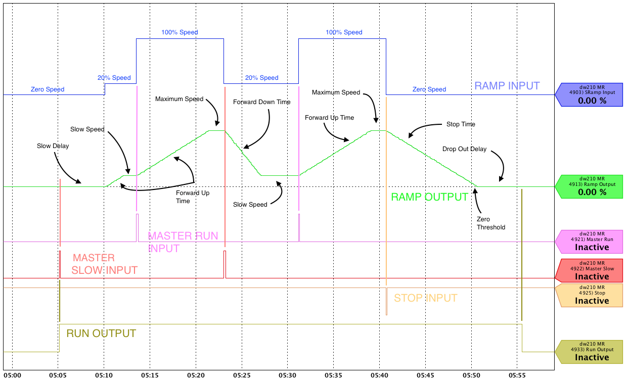 Jog ModeThe basic sequence of events for Jogging Mode follows: StoppedThe idle state of the ramp. The Ramp Output is zero and the Run Output is Inactive.Jog DelayUpon entering Jog Mode (by asserting either Master Jog 1 or Master Jog 2), the user settable Jog Delay timer begins timing while the Ramp Output is held at zero.JoggingOnce the Jog Delay timer has expired, the Ramp Output is released and will ramp up using either Jog 1 Ramp Time/S Percent or Jog 2 Ramp Time/S Percent depending on the selected Master Jog input.Jog StoppingIf in Jog Mode and both Master Jog 1 and Master Jog 2 become Inactive, the Ramp Output will ramp towards zero on the appropriate Jog Ramp Time/S Percent.Dropping OutThe Ramp Output is held at zero speed for the duration of the Drop Out Delay. If the Drop Out Delay timer expires, the ramp returns to the normal Stopped state. If any of the run inputs are re-asserted while the timer is still timing, the ramp will re-initiate the appropriate delay for the selected mode (just as if starting from the Stopped state).Jog Mode Trend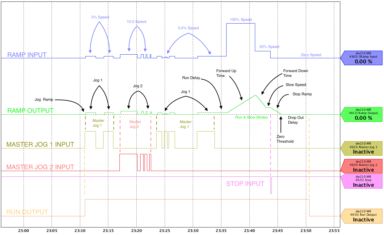 Miscellaneous
Additional Information |
|||||||||||||||||||||||||||||||||||||||||||||||||||||||||||||||||||||||||||
| Availability |
|
|||||||||||||||||||||||||||||||||||||||||||||||||||||||||||||||||||||||||||
| savvy-SFD Graphic | 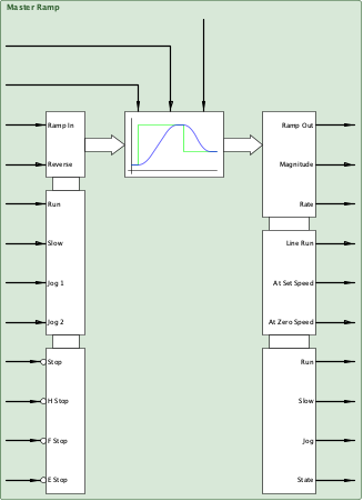 |
|||||||||||||||||||||||||||||||||||||||||||||||||||||||||||||||||||||||||||
| Graphic with Parameters | 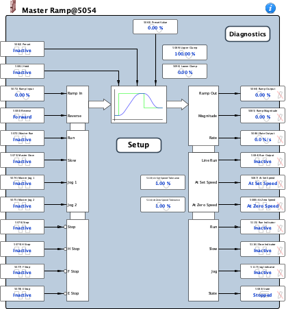 |
| S Ramp Input |
Internal Parameter, Read-only, Set to default on hard initialization, Analog (signed 16-bit integer) -327.67 % to 327.67 % |
|||||||||||||||||||||||||||||||||||||||||
| S Ramp Forward Up Time |
Internal Parameter, Read-only, Time or Rate (signed 16-bit integer) 0.1 s to 3000.0 s Minimum time for the ramp to change by 100% when the input is positive and moving away from zero. |
|||||||||||||||||||||||||||||||||||||||||
| S Ramp Forward Down Time |
Internal Parameter, Read-only, Time or Rate (signed 16-bit integer) 0.1 s to 3000.0 s Minimum time for the ramp to change by 100% when the output is positive and moving toward zero. |
|||||||||||||||||||||||||||||||||||||||||
| S Ramp Reverse Down Time |
Internal Parameter, Read-only, Time or Rate (signed 16-bit integer) 0.1 s to 3000.0 s Minimum time for the ramp to change by 100% when the output is negative and moving toward zero. |
|||||||||||||||||||||||||||||||||||||||||
| S Ramp Reverse Up Time |
Internal Parameter, Read-only, Time or Rate (signed 16-bit integer) 0.1 s to 3000.0 s Minimum time for the ramp to change by 100% when the output is negative and moving away from zero. |
|||||||||||||||||||||||||||||||||||||||||
| S Ramp S Percent |
Internal Parameter, Read-only, Analog (signed 16-bit integer) 0.01 % to 100.00 % Specifies how much of the ramp time will be spent in the S part of the curve. 0% means a linear ramp, 100% means all S. Note that increasing the S Percent will increase the maximum rate of change of the ramp. |
|||||||||||||||||||||||||||||||||||||||||
| S Ramp Hold Enable |
Internal Parameter, Read-only, Boolean (signed 16-bit integer) Immediately holds the ramp at its current value. Hold Enable simply suspends processing of the ramp. 0 = Inactive 1 = Hold |
|||||||||||||||||||||||||||||||||||||||||
| S Ramp Reset Enable |
Internal Parameter, Read-only, Boolean (signed 16-bit integer) Immediately sets the output to zero and resets the S calculations 0 = Inactive 1 = Reset |
|||||||||||||||||||||||||||||||||||||||||
| S Ramp Preset Enable |
Internal Parameter, Read-only, Boolean (signed 16-bit integer) Immediately sets the ramp output to Preset Value and resets the S calculations 0 = Inactive 1 = Preset |
|||||||||||||||||||||||||||||||||||||||||
| Preset Value |
Input, Read-write, Analog (signed 16-bit integer) -327.67 % to 327.67 % This parameter sets the value to which the Ramp Output will ramp when the Preset input is asserted.
The Prep. is an abbreviation for Prepare for which generally means there is a time delay before entering the next state. The (S) indicates a Prep. from the Stopped state while the (J) indicates a Prep. from the Jog state. The - (hypen) in the table indicates an Ignore condition. |
|||||||||||||||||||||||||||||||||||||||||
| Ramp Output |
Output, Read-only, Set to default on hard initialization, Analog (signed 16-bit integer) -327.67 % to 327.67 % This output is the current value of the ramp based on the mode of operation. |
|||||||||||||||||||||||||||||||||||||||||
| S Ramp Rate Output |
Internal Parameter, Read-only, Analog (signed 16-bit integer) -3276.7 %/s to 3276.7 %/s |
|||||||||||||||||||||||||||||||||||||||||
| Ramp Input |
Input, Read-write, Analog (signed 16-bit integer) -327.67 % to 327.67 % This parameter sets the desired speed while in Running mode. Typically, the input has a drive.web connection to the real world via an analog input, a motor operated potentiometer (MOP) function block, or a dw230 savvyPanel touchscreen.
The Prep. prefix is an abbreviation for Prepare for which generally means there is a time delay before entering the next state. The (S) indicates a Prep. from the Stopped state while the (J) indicates a Prep. from the Jog state. |
|||||||||||||||||||||||||||||||||||||||||
| Master Run |
Input, Read-write, Boolean (signed 16-bit integer) When this input is Active (High) and ALL of the Stop Inputs are Inactive (High), the ramp will enter the Running state and the output will ramp to the Ramp Input setting. The Running Inputs order of precedence is: 0 = Inactive 1 = Run |
|||||||||||||||||||||||||||||||||||||||||
| Master Slow |
Input, Read-write, Boolean (signed 16-bit integer) When this input is Active (High) and ALL of the Stop Inputs are Inactive (High), the ramp will enter the Slow Running state and will ramp to the Slow Speed setting. The Running Inputs in order of precedence is: 0 = Inactive 1 = Slow |
|||||||||||||||||||||||||||||||||||||||||
| Master Jog 1 |
Input, Read-write, Boolean (signed 16-bit integer) When this input is Active (High) and ALL of the Stop Inputs are Inactive (High), the ramp will enter the Jogging state and will ramp to the Jog Speed 1 setting. The Running Inputs order of precedence is: 0 = Inactive 1 = Jog |
|||||||||||||||||||||||||||||||||||||||||
| Master Jog 2 |
Input, Read-write, Boolean (signed 16-bit integer) When this input is Active (High) and ALL of the Stop Inputs are Inactive (High), the ramp will enter the Jogging state and will ramp to the Jog Speed 2 setting. The Running Inputs order of precedence is: 0 = Inactive 1 = Jog |
|||||||||||||||||||||||||||||||||||||||||
| Stop |
Input, Read-write, Boolean (signed 16-bit integer) When this input is Active (Low), the Ramp Input will be set to zero and the output will ramp to zero using the Stop Ramp Time/S Percent. When the output falls below the At Zero Speed Tolerance, the Drop Out Delay begins. The Stopping Inputs order of precedence is: 0 = Stop 1 = Inactive |
|||||||||||||||||||||||||||||||||||||||||
| F Stop |
Input, Read-write, Boolean (signed 16-bit integer) When this input is Active (Low), the Ramp Input will be set to zero and the output will ramp to zero using the F Stop Ramp Time/S Percent. When the output falls below the At Zero Speed Tolerance, the Drop Out Delay begins. The Stopping Inputs order of precedence is: 0 = Stop 1 = Inactive |
|||||||||||||||||||||||||||||||||||||||||
| E Stop |
Input, Read-write, Boolean (signed 16-bit integer) This Stopping Input has the highest priority and overrides H Stop, F Stop, and Stop. When Active (Low), the Ramp Output will be immediately set to zero and the Run Output will be made Inactive. The Master Ramp goes directly to the Stopped state bypassing the Drop Out Delay. The Stopping Inputs order of precedence is: 0 = Stop 1 = Inactive |
|||||||||||||||||||||||||||||||||||||||||
| H Stop |
Input, Read-write, Boolean (signed 16-bit integer) When this input is Active (Low), the Ramp Input will be set to zero and the output will ramp to zero using the H Stop Ramp Time/S Percent. When the output falls below the At Zero Speed Tolerance, the Drop Out Delay begins. The Stopping Inputs order of precedence is: 0 = Stop 1 = Inactive |
|||||||||||||||||||||||||||||||||||||||||
| Reverse |
Input, Read-write, Boolean (signed 16-bit integer) When this input is Active (High), the SRamp Input is inverted. The inversion applies to all of the reference sources (Ramp Input, Slow Speed, Jog Speed 1, and Jog Speed 2). While Active, for a positive reference, the Ramp Output will be negative and vice versa. 0 = Forward 1 = Reverse |
|||||||||||||||||||||||||||||||||||||||||
| Hold |
Input, Read-write, Boolean (signed 16-bit integer) When this input is Active (High) and in the Running state, this input freezes the Ramp Output at the current value. If any Stop is Active it overrides the state of this input and the Ramp Output ramps towards zero on the appropriate ramp; however, if Master Run or Master Slow is re-asserted prior to the Ramp Output reaching zero, the ramp will freeze at the last value as long as this input is still Active.
The Prep. is an abbreviation for Prepare for which generally means there is a time delay before entering the next state. The (S) indicates a Prep. from the Stopped state while the (J) indicates a Prep. from the Jog state. The - (hypen) in the table indicates an Ignore condition. 0 = Inactive 1 = Hold |
|||||||||||||||||||||||||||||||||||||||||
| Preset |
Input, Read-write, Boolean (signed 16-bit integer)
When this input is Active (High) and the Master Ramp is in the Running state, the Ramp Output is immediately set to the Preset Value. If any Stop is Active it overrides the state of this input.
The Prep. prefix is an abbreviation for Prepare for which generally means there is a time delay before entering the next state. The (S) indicates a Prep. from the Stopped state while the (J) indicates a Prep. from the Jog state. The - (hypen) in the table indicates an Ignore condition. 0 = Inactive 1 = Preset |
|||||||||||||||||||||||||||||||||||||||||
| State |
Output, Read-only, Set to default on hard initialization, Enumerated (signed 16-bit integer) This parameter reflects the active state of the Master Ramp. Lacking any transitional inputs, the default state is Stopped. 0 = Stopped 1 = Prep. Run (S) 2 = Prep. Run (J) 3 = Running 4 = Prep. Slow (S) 5 = Prep. Slow (J) 6 = Slow Running 7 = Prep. Jog 8 = Jogging 9 = Stopping 10 = H Stopping 11 = F Stopping 12 = Dropping Out 13 = Jog Stopping |
|||||||||||||||||||||||||||||||||||||||||
| Run Output |
Output, Read-only, Set to default on hard initialization, Boolean (signed 16-bit integer) This output is ON in the Running, Slow Running, and Jog modes and their associated transitional states. The Stopped state is the only state where this output is OFF. Typically, this output is used for a coordinated start signal to equipment using the Ramp Output of the Master Ramp. 0 = Inactive 1 = Run |
|||||||||||||||||||||||||||||||||||||||||
| Ramp Magnitude |
Output, Read-only, Set to default on hard initialization, Analog (signed 16-bit integer) 0.00 % to 327.67 % This output is the absolute value of the Ramp Output. Typical uses are with comparator function blocks or non-reversing follower sections. |
|||||||||||||||||||||||||||||||||||||||||
| Rate Output |
Output, Read-only, Set to default on hard initialization, Analog (signed 16-bit integer) -3276.7 %/s to 3276.7 %/s This output is the 1st derivative of the Ramp Output (i.e. the slope of the output curve based on the ramp time settings). This output is useful when a signal proportional to the rate of change of the Ramp Output is required (e.g, when implementing a predicitve inertia compensation scheme). At a fixed speed, this output is zero. For a positive (+) Ramp Output, the rate is positive (+) while ramping up and negative (-) while ramping down. Conversely, for a negative (-) Ramp Output, the rate is negative (-) while ramping up (i.e., more negative) and positive (+) while ramping down (i.e., less negative). |
|||||||||||||||||||||||||||||||||||||||||
| At Set Speed |
Output, Read-only, Boolean (signed 16-bit integer) This output indicates the Ramp Output is equal to the S Ramp Input within a window defined by the At Set Speed Tolerance. 0 = Inactive 1 = At Set Speed |
|||||||||||||||||||||||||||||||||||||||||
| At Zero Speed |
Output, Read-only, Boolean (signed 16-bit integer) This output indicates the Ramp Output is equal to zero within a window defined by the At Zero Speed Tolerance. 0 = Inactive 1 = At Zero Speed |
|||||||||||||||||||||||||||||||||||||||||
| Upper Clamp |
Internal Parameter, Read-write, Analog (signed 16-bit integer) 0.00 % to 327.67 % This parameter sets the absolute positive limit of the Ramp Output regardless of the value of the Ramp Input or any of the presets (i.e. Slow Speed, Jog Speed 1, or Jog Speed 2). |
|||||||||||||||||||||||||||||||||||||||||
| Lower Clamp |
Internal Parameter, Read-write, Analog (signed 16-bit integer) -327.67 % to 327.67 % This parameter sets the absolute lower limit of the Ramp Output regardless of the value of the Ramp Input or any of the presets (i.e. Slow Speed, Jog Speed 1, or Jog Speed 2). |
|||||||||||||||||||||||||||||||||||||||||
| Jog Speed 1 |
Internal Parameter, Read-write, Analog (signed 16-bit integer) -327.67 % to 327.67 % This parameter is the preset value used when Master Jog 1 is Active.
The Prep. prefix is an abbreviation for Prepare for which generally means there is a time delay before entering the next state. The (S) indicates a Prep. from the Stopped state while the (J) indicates a Prep. from the Jog state. |
|||||||||||||||||||||||||||||||||||||||||
| Jog Speed 2 |
Internal Parameter, Read-write, Analog (signed 16-bit integer) -327.67 % to 327.67 % This parameter is the preset value used when Master Jog 2 is Active.
The Prep. prefix is an abbreviation for Prepare for which generally means there is a time delay before entering the next state. The (S) indicates a Prep. from the Stopped state while the (J) indicates a Prep. from the Jog state. |
|||||||||||||||||||||||||||||||||||||||||
| Slow Speed |
Internal Parameter, Read-write, Analog (signed 16-bit integer) -327.67 % to 327.67 % This parameter is the preset value used when Master Slow is Active.
The Prep. prefix is an abbreviation for Prepare for which generally means there is a time delay before entering the next state. The (S) indicates a Prep. from the Stopped state while the (J) indicates a Prep. from the Jog state. |
|||||||||||||||||||||||||||||||||||||||||
| Run Delay |
Internal Parameter, Read-write, Analog (unsigned 16-bit integer) 0.1 s to 10.0 s This parameter sets the delay time before entering Running mode. During the delay, the Run Output is activated while Ramp Output is held at zero. |
|||||||||||||||||||||||||||||||||||||||||
| Drop Out Delay |
Internal Parameter, Read-write, Analog (unsigned 16-bit integer) 0.5 s to 20.0 s |
|||||||||||||||||||||||||||||||||||||||||
| Slow Delay |
Internal Parameter, Read-write, Analog (unsigned 16-bit integer) 0.1 s to 10.0 s This parameter sets the delay time before entering Slow Running mode. During the delay, the Run Output is activated while Ramp Output is held at zero. |
|||||||||||||||||||||||||||||||||||||||||
| Jog Delay |
Internal Parameter, Read-write, Analog (unsigned 16-bit integer) 0.1 s to 10.0 s This parameter sets the delay time before entering Jog mode. During the delay, the Run Output is activated while Ramp Output is held at zero. |
|||||||||||||||||||||||||||||||||||||||||
| Forward Up Time |
Internal Parameter, Read-write, Time or Rate (signed 16-bit integer) 0.1 s to 3000.0 s If the ramp is in either the Running or Slow Running modes, this parameter sets the total time to change the Ramp Output from zero to 100%. If the Ramp Input is greater (or less) than 100%, the time will be proportionally longer (shorter) (e.g., for a 150% Ramp Input the actual time will be 1.5 times this setting). |
|||||||||||||||||||||||||||||||||||||||||
| Forward Down Time |
Internal Parameter, Read-write, Time or Rate (signed 16-bit integer) 0.1 s to 3000.0 s If the ramp is in either the Running or Slow Running mode, this parameter sets the total time to change the Ramp Output from 100% to zero. If the Ramp Output is greater (or less) than 100%, the time will be proportionally longer (shorter) (e.g., for a 150% Ramp Output the actual time will be 1.5 times this setting). |
|||||||||||||||||||||||||||||||||||||||||
| Reverse Down Time |
Internal Parameter, Read-write, Time or Rate (signed 16-bit integer) 0.1 s to 3000.0 s If the ramp is in either the Running or Slow Running modes, this parameter sets the total time to change the Ramp Output from -100% to zero. If the Ramp Output is arithmetically less (or greater) than -100%, the time will be proportionally longer (shorter) (e.g., for a -150% Ramp Output the actual time will be 1.5 times this setting). |
|||||||||||||||||||||||||||||||||||||||||
| Reverse Up Time |
Internal Parameter, Read-write, Time or Rate (signed 16-bit integer) 0.1 s to 3000.0 s If the ramp is in either the Running or Slow Running modes, this parameter sets the total time to change the Ramp Output from zero to -100%. If the Ramp Output is arithmetically less (or greater) than -100%, the time will be proportionally longer (shorter) (e.g., for a -150% Ramp Input the actual time will be 1.5 times this setting). |
|||||||||||||||||||||||||||||||||||||||||
| Jog 1 Ramp Time |
Internal Parameter, Read-write, Time or Rate (signed 16-bit integer) 0.1 s to 3000.0 s This parameter sets the time desired to ramp from zero to Jog Speed 1. The setting is used while Master Jog 1 is Active and when stopping from the jog speed. The time is specified as the total time to change the Ramp Output from zero to 100%. So, if Jog Speed 1 is set to 5.00% and this parameter is set to 5.0s, the actual time to reach Jog Speed 1 is 0.25s ( [Jog Speed 1 ÷ 100] × Jog 1 Ramp Time). |
|||||||||||||||||||||||||||||||||||||||||
| Jog 2 Ramp Time |
Internal Parameter, Read-write, Time or Rate (signed 16-bit integer) 0.1 s to 3000.0 s This parameter sets the time desired to ramp from zero to Jog Speed 2. The setting is used while Master Jog 2 is Active and when stopping from the jog speed. The time is specified as the total time to change the Ramp Output from zero to 100%. So, if Jog Speed 2 is set to 10.00% and this parameter is set to 5.0s, the actual time to reach Jog Speed 2 is 0.5s ( [Jog Speed 2 ÷ 100] × Jog 2 Ramp Time ). |
|||||||||||||||||||||||||||||||||||||||||
| Stop Ramp Time |
Internal Parameter, Read-write, Time or Rate (signed 16-bit integer) 0.1 s to 3000.0 s If no higher priority Stopping Input is asserted, this parameter sets the total time to change the Ramp Output from 100% to zero. If the Ramp Output is greater (or less) than 100%, the time will be proportionally longer (shorter) (e.g., for a 150% Ramp Output the time will be 1.5 times this setting). The Stopping Inputs order of precedence is: |
|||||||||||||||||||||||||||||||||||||||||
| F Stop Ramp Time |
Internal Parameter, Read-write, Time or Rate (signed 16-bit integer) 0.1 s to 3000.0 s If no higher priority Stopping Input is asserted, this parameter sets the total time to change the Ramp Output from 100% to zero. If the Ramp Output is greater (or less) than 100%, the time will be proportionally longer (shorter) (e.g., for a 150% Ramp Output the time will be 1.5 times this setting). The Stopping Inputs order of precedence is: |
|||||||||||||||||||||||||||||||||||||||||
| H Stop Ramp Time |
Internal Parameter, Read-write, Time or Rate (signed 16-bit integer) 0.1 s to 3000.0 s If no higher priority Stopping Input is asserted, this parameter sets the total time to change the Ramp Output from 100% to zero. If the Ramp Output is greater (or less) than 100%, the time will be proportionally longer (shorter) (e.g., for a 150% Ramp Output the time will be 1.5 times this setting). The Stopping Inputs order of precedence is: |
|||||||||||||||||||||||||||||||||||||||||
| Run S Percent |
Internal Parameter, Read-write, Analog (signed 16-bit integer) 0.01 % to 100.00 % This parameter is used to round off the end-points of the Ramp Output as the desired speed is approached. The result is a smoother transition to a constant speed with minimal overshoot. The S Percent setting is the percentage of the total time that will be spent in the S-portion of the curve. A setting of 0% results in no S-function which yields a linear ramp similar to the Acceleration plot below. A setting of 100% results in the entire ramp being in the S-portion of the curve. For a non-zero S Percent setting, the ramp end-points will be rounded proportional to the setting much like the Speed curve below. Note: To keep the overall ramp time the same when the S Percent is non-zero, the rate of change of the ramp must be increased in the non-S portion of the curve resulting in a higher Rate Output. 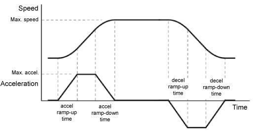 |
|||||||||||||||||||||||||||||||||||||||||
| Jog 1 S Percent |
Internal Parameter, Read-write, Analog (signed 16-bit integer) 0.01 % to 100.00 % This parameter is used to round off the end-points of the Ramp Output as the desired speed is approached. The result is a smoother transition to a constant speed with minimal overshoot. The S Percent setting is the percentage of the total time that will be spent in the S-portion of the curve. A setting of 0% results in no S-function which yields a linear ramp similar to the Acceleration plot below. A setting of 100% results in the entire ramp being in the S-portion of the curve. For a non-zero S Percent setting, the ramp end-points will be rounded proportional to the setting much like the Speed curve below. Note: To keep the overall ramp time the same when the S Percent is non-zero, the rate of change of the ramp must be increased in the non-S portion of the curve resulting in a higher Rate Output. |
|||||||||||||||||||||||||||||||||||||||||
| Jog 2 S Percent |
Internal Parameter, Read-write, Analog (signed 16-bit integer) 0.01 % to 100.00 % This parameter is used to round off the end-points of the Ramp Output as the desired speed is approached. The result is a smoother transition to a constant speed with minimal overshoot. The S Percent setting is the percentage of the total time that will be spent in the S-portion of the curve. A setting of 0% results in no S-function which yields a linear ramp similar to the Acceleration plot below. A setting of 100% results in the entire ramp being in the S-portion of the curve. For a non-zero S Percent setting, the ramp end-points will be rounded proportional to the setting much like the Speed curve below. Note: To keep the overall ramp time the same when the S Percent is non-zero, the rate of change of the ramp must be increased in the non-S portion of the curve resulting in a higher Rate Output. |
|||||||||||||||||||||||||||||||||||||||||
| Stop S Percent |
Internal Parameter, Read-write, Analog (signed 16-bit integer) 0.01 % to 100.00 % This parameter is used to round off the end-points of the Ramp Output as the desired speed is approached. The result is a smoother transition to a constant speed with minimal overshoot. The S Percent setting is the percentage of the total time that will be spent in the S-portion of the curve. A setting of 0% results in no S-function which yields a linear ramp similar to the Acceleration plot below. A setting of 100% results in the entire ramp being in the S-portion of the curve. For a non-zero S Percent setting, the ramp end-points will be rounded proportional to the setting much like the Speed curve below. Note: To keep the overall ramp time the same when the S Percent is non-zero, the rate of change of the ramp must be increased in the non-S portion of the curve resulting in a higher Rate Output. |
|||||||||||||||||||||||||||||||||||||||||
| F Stop S Percent |
Internal Parameter, Read-write, Analog (signed 16-bit integer) 0.01 % to 100.00 % This parameter is used to round off the end-points of the Ramp Output as the desired speed is approached. The result is a smoother transition to a constant speed with minimal overshoot. The S Percent setting is the percentage of the total time that will be spent in the S-portion of the curve. A setting of 0% results in no S-function which yields a linear ramp similar to the Acceleration plot below. A setting of 100% results in the entire ramp being in the S-portion of the curve. For a non-zero S Percent setting, the ramp end-points will be rounded proportional to the setting much like the Speed curve below. Note: To keep the overall ramp time the same when the S Percent is non-zero, the rate of change of the ramp must be increased in the non-S portion of the curve resulting in a higher Rate Output. |
|||||||||||||||||||||||||||||||||||||||||
| H Stop S Percent |
Internal Parameter, Read-write, Analog (signed 16-bit integer) 0.01 % to 100.00 % This parameter is used to round off the end-points of the Ramp Output as the desired speed is approached. The result is a smoother transition to a constant speed with minimal overshoot. The S Percent setting is the percentage of the total time that will be spent in the S-portion of the curve. A setting of 0% results in no S-function which yields a linear ramp similar to the Acceleration plot below. A setting of 100% results in the entire ramp being in the S-portion of the curve. For a non-zero S Percent setting, the ramp end-points will be rounded proportional to the setting much like the Speed curve below. Note: To keep the overall ramp time the same when the S Percent is non-zero, the rate of change of the ramp must be increased in the non-S portion of the curve resulting in a higher Rate Output. |
|||||||||||||||||||||||||||||||||||||||||
| At Set Speed Tolerance |
Internal Parameter, Read-write, Analog (signed 16-bit integer) 0.00 % to 100.00 % This parameter sets the tolerance (+/-) on the window of the equality comparison between the Ramp Output and the S Ramp Input which controls the At Set Speed output. |
|||||||||||||||||||||||||||||||||||||||||
| At Zero Speed Tolerance |
Internal Parameter, Read-write, Analog (signed 16-bit integer) 0.00 % to 100.00 % This parameter sets the tolerance (+/-) on the window of the equality comparison between the Ramp Output and zero which controls the At Zero Speed output. |
|||||||||||||||||||||||||||||||||||||||||
| Run Indicator |
Output, Read-only, Set to default on hard initialization, Boolean (signed 16-bit integer) This output is ON while the ramp is in Running Mode (i.e., during the Prep. Run (S), Prep Run (J), and Running states).
The Prep. is an abbreviation for Prepare for which generally means there is a time delay before entering the next state. The (S) indicates a Prep. from the Stopped state while the (J) indicates a Prep. from the Jog state. The - (hypen) in the table indicates an Off condition. 0 = Inactive 1 = Run |
|||||||||||||||||||||||||||||||||||||||||
| Slow Indicator |
Output, Read-only, Set to default on hard initialization, Boolean (signed 16-bit integer) This output is ON while the ramp is in Slow Running Mode (i.e., during the Prep. Slow (S), Prep Slow (J), and Slow Running states).
The Prep. is an abbreviation for Prepare for which generally means there is a time delay before entering the next state. The (S) indicates a Prep. from the Stopped state while the (J) indicates a Prep. from the Jog state. The - (hypen) in the table indicates an Off condition. 0 = Inactive 1 = Slow |
|||||||||||||||||||||||||||||||||||||||||
| Jog Indicator |
Output, Read-only, Set to default on hard initialization, Boolean (signed 16-bit integer) This output is ON while the ramp is in Jog Mode (i.e., during the Prep. Jog and Jogging states).
The Prep. is an abbreviation for Prepare for which generally means there is a time delay before entering the next state. The (S) indicates a Prep. from the Stopped state while the (J) indicates a Prep. from the Jog state. The - (hypen) in the table indicates an Off condition. 0 = Inactive 1 = Jog |