|
Encoder
ENC Status Monitor
|
| Description | This function block gives the user a detailed summary of the status of one (or both) of the encoder(s). Included in the encoder status are:
|
| Availability |
|
| savvy-SFD Graphic |  |
| Graphic with Parameters |
| ENC1 Comms State |
Internal Parameter, Read-only, Boolean (signed 16-bit integer) This parameter reflects the status of the communication channel to either the internal encoder (dwOption -15) or to an External Encoder Module (dwOptions -40 through -46). For normal operation, the ENC1 Comms State must indicate an OK state. If communications is lost for at least 20 milliseconds, a Fault is indicated. If the problem persists check for voltage variations on the module's power supply and the I2I Encoder Interface Port cabling. 0 = OK 1 = Fault |
| ENC DIN1 State |
Internal Parameter, Read-only, Boolean (signed 16-bit integer) Indicates the current status of DIN1 (Terminal E4). The transition level is 8.2 Vdc (+/-7%). 0 = Low 1 = High |
| ENC1 A State |
Internal Parameter, Read-only, Boolean (signed 16-bit integer) Indicates the current status of the input channel.
0 = Low 1 = High |
| ENC1 B State |
Internal Parameter, Read-only, Boolean (signed 16-bit integer) Indicates the current status of the input channel.
0 = Low 1 = High |
| ENC1 Z State |
Internal Parameter, Read-only, Boolean (signed 16-bit integer) Indicates the current status of the input channel.
0 = Low 1 = High |
| ENC1 Direction |
Internal Parameter, Read-only, Boolean (signed 16-bit integer) This parameter indicates the relationship of encoder channel A with respect to encoder channel B. To change the indication for a particular direction of rotation, swap A and -A on the input terminals. 0 = Forward 1 = Reverse |
| ENC1 A Alarm |
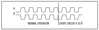
Internal Parameter, Read-only, Boolean (signed 16-bit integer) For proper operation, this parameter must read OK and indicates the presence of the input channel and its complement. If an Alarm state is indicated, the associated function blocks will behave as follows:
These actions are considered the safest behavior for the associated application; however, as you may expect, the system's performance will suffer during the Alarm state. For critical applications, a drive.web connection may be made from this parameter to any alarm handling logic designed by the user. If the alarm clears, the Status will immediately return to OK (i.e., alarm conditions are not latched). Possible causes for an Alarm state are shown below:
0 = OK 1 = Alarm |
| ENC1 B Alarm |
Internal Parameter, Read-only, Boolean (signed 16-bit integer) For proper operation, this parameter must read OK and indicates the presence of the input channel and its complement. If an Alarm state is indicated, the associated function blocks will behave as follows:
These actions are considered the safest behavior for the associated application; however, as you may expect, the system's performance will suffer during the Alarm state. For critical applications, a drive.web connection may be made from this parameter to any alarm handling logic designed by the user. If the alarm clears, the Status will immediately return to OK (i.e., alarm conditions are not latched). Possible causes for an Alarm state are shown below:
0 = OK 1 = Alarm |
| ENC1 Z Alarm |
Internal Parameter, Read-only, Boolean (signed 16-bit integer) If the Z channel is used, this parameter must read OK indicating the presence of the input channel and its complement. If desired, this parameter may connected to user logic so the appropriate action may be taken when an Alarm state is indicated. When the alarm clears, the Status will immediately return to an OK state (i.e., alarm conditions are not latched). Possible causes for an Alarm state are shown below:
0 = OK 1 = Alarm |
| ENC2 Comms State |
Internal Parameter, Read-only, Boolean (signed 16-bit integer) This parameter reflects the status of the communication channel to either the internal encoder (dwOption -15) or to an External Encoder Module (dwOptions -40 through -46). For normal operation, the ENC2 Comms State must indicate an OK state. If communications is lost for at least 20 milliseconds, a Fault is indicated. If the problem persists check for voltage variations on the module's power supply and the I2I Encoder Interface Port cabling. 0 = OK 1 = Fault |
| ENC DIN2 State |
Internal Parameter, Read-only, Boolean (signed 16-bit integer) Indicates the current status of DIN2 (Terminal E5). The transition level is 8.2 Vdc (+/-7%). 0 = Low 1 = High |
| ENC2 A State |
Internal Parameter, Read-only, Boolean (signed 16-bit integer) Indicates the current status of the input channel.
0 = Low 1 = High |
| ENC2 B State |
Internal Parameter, Read-only, Boolean (signed 16-bit integer) Indicates the current status of the input channel.
0 = Low 1 = High |
| ENC2 Z State |
Internal Parameter, Read-only, Boolean (signed 16-bit integer) Indicates the current status of the input channel.
0 = Low 1 = High |
| ENC2 Direction |
Internal Parameter, Read-only, Boolean (signed 16-bit integer) This parameter indicates the relationship of encoder channel A with respect to encoder channel B. To change the indication for a particular direction of rotation, swap A and -A on the input terminals. 0 = Forward 1 = Reverse |
| ENC2 A Alarm |
Internal Parameter, Read-only, Boolean (signed 16-bit integer) For proper operation, this parameter must read OK and indicates the presence of the input channel and its complement. If an Alarm state is indicated, the associated function blocks will behave as follows:
These actions are considered the safest behavior for the associated application;however, as you may expect, the system's performance will suffer during the Alarm state. For critical applications, a drive.web connection may be made from this parameter to any alarm handling logic designed by the user. If the alarm clears, the Status will immediately return to OK (i.e., alarm conditions are not latched). Possible causes for an Alarm state are shown below:
0 = OK 1 = Alarm |
| ENC2 B Alarm |
Internal Parameter, Read-only, Boolean (signed 16-bit integer) For proper operation, this parameter must read OK and indicates the presence of the input channel and its complement. If an Alarm state is indicated, the associated function blocks will behave as follows:
These actions are considered the safest behavior for the associated application; however, as you may expect, the system's performance will suffer during the Alarm state. For critical applications, a drive.web connection may be made from this parameter to any alarm handling logic designed by the user. If the alarm clears, the Status will immediately return to OK (i.e., alarm conditions are not latched). Possible causes for an Alarm state are shown below:
0 = OK 1 = Alarm |
| ENC2 Z Alarm |
Internal Parameter, Read-only, Boolean (signed 16-bit integer) If the Z channel is used, this parameter must read OK indicating the presence of the input channel and its complement. If desired, this parameter may connected to user logic so the appropriate action may be taken when an Alarm state is indicated. When the alarm clears, the Status will immediately return to an OK state (i.e., alarm conditions are not latched). Possible causes for an Alarm state are shown below:
0 = OK 1 = Alarm |
| Comms Errors |
Internal Parameter, Read-only, Analog (unsigned 16-bit integer) 0 to 65535 This parameter keeps a tally of total errors on the communication link effectively recording every transition of the ENC1 Comms State and ENC2 Comms State. |