
|
Encoder
ENC Indexed Position
|
| Description | This function block is used to both calibrate the index positions of the cyclic position application and to select the Desired Position in the cycle when moving between index positions. The calibration portion of the block arithmetically calculates the Index Length based on the Current Position and the Setup Index. The calculation is performed as follows: If an ENC Position Point function block is the associated ENC Reference Position selection, the value for the Reference Position is the stored 64-bit Position Point value which, in turn, is referenced to the Cycle Zero position. If an ENC# Cyclic Position function block is the associated ENC Reference Position selection, the Reference Position is also the Cycle Zero. Using the Index Length, the position selection portion uses the Index value to calculate a Desired Position. The Desired Position value (with the appropriate Reference Position offset ) is then compared to the Current Position generating a Position Error output. The output may then be used for control purposes. A Position Error value of 0.00% indicates you are in the Desired Position. 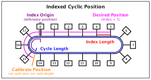 The Index Length may be set in two ways:
After calibration, selecting the Desired Position is achieved by simply setting the Index to the appropriate value. In this example, setting the Index to Position 5. The magenta path above represents the 64-bit count associated with the Desired Position and is calculated as follows: Resulting in a Position Error calculated as follows: |
| Availability |
|
| savvy-SFD Graphic | 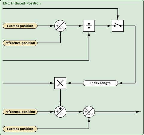 |
| Graphic with Parameters | 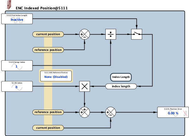 |
| ENC Reference Position |
Internal Parameter, Read-write, Function Block Association (signed 16-bit integer) This function block may be associated with the following position control function blocks:
In either case, the Cycle Length used in the Index Length calculation is obtained either directly from the ENC# Cyclic Position function block or inherited via the ENC Position Point function block. |
| Set Index Length |
Input, Read-write, Boolean (signed 16-bit integer) When this parameter is Set, the 64-bit value calculated by the calibration portion of the function block will be loaded into the Index Length. The Index Length is calculated as follows: 0 = Inactive 1 = Set |
| Setup Index |
Input, Read-write, Analog (unsigned 16-bit integer) 1 to 65535 Set this value to the Index associated with the stop position prior to activating the Set Index Length input to calibrate the function block. This value is then used to calculate the Index Length to be used for positioning control. In most applications, the distance between stop positions is a fixed, constant value. However, it is possible to use varying indices as long as all of the stop positions are defined as some integer multiple of the Index Length. 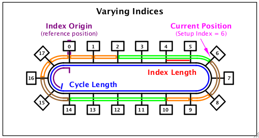 In this example, we have three different bin sizes which will require moves of different lengths to position properly:
To calibrate the Index Length for these varying indices applications, the Setup Index must be set properly for the associated position. For the fourth bin position above, the Setup Index must be set to 6 prior to activating the Set Index Length input to calculate the proper Index Length. |
| Index Length 0 |
Internal Parameter, Read-write, Hexadecimal (unsigned 16-bit integer) 0x0 to 0xFFFF Least significant 16-bits of the current 64-bit Index Length which reflects distance between adjacent indices. Concatenate the hexadecimal values to determine the total count. For example, 0x0000 0x0BA8 0x9DE7 0x3694 = 12,818,831,586,964. |
| Index Length 1 |
Internal Parameter, Read-write, Hexadecimal (unsigned 16-bit integer) 0x0 to 0xFFFF Most, least significant 16-bits of the current 64-bit Index Length which reflects distance between adjacent indices. Concatenate the hexadecimal values to determine the total count. For example, 0x0000 0x0BA8 0x9DE7 0x3694 = 12,818,831,586,964. |
| Index Length 2 |
Internal Parameter, Read-write, Hexadecimal (unsigned 16-bit integer) 0x0 to 0xFFFF Least, most significant 16-bits of the current 64-bit Index Length which reflects distance between adjacent indices. Concatenate the hexadecimal values to determine the total count. For example, 0x0000 0x0BA8 0x9DE7 0x3694 = 12,818,831,586,964. |
| Index Length 3 |
Internal Parameter, Read-write, Hexadecimal (unsigned 16-bit integer) 0x0 to 0xFFFF Most significant 16-bits of the current 64-bit Index Length which reflects distance between adjacent indices. Concatenate the hexadecimal values to determine the total count. For example, 0x0000 0x0BA8 0x9DE7 0x3694 = 12,818,831,586,964. |
| Index |
Input, Read-write, Analog (unsigned 16-bit integer) 0 to 65535 This parameter sets the multiplier for the Desired Position calculation. If the value exceeds the actual number of positions in the cycle, the resulting move will be the number of complete cycles contained in the Index setting with the final position determined by the remainder. For example, if the actual number of positions is 18 and the Index is set to 25, the move would be one complete cycle with the final location of Position 7. |
| Position Error |
Output, Read-only, Analog (signed 16-bit integer) -327.67 % to 327.67 % The Position Error is generated by comparing the Desired Position to the Current Position as follows: If the Position Error exceeds +/- 327.66%, the parameter will indicate overrange; however, the 64-bit Internal Count is unaffected. -32767 = - overrange 32767 = + overrange |