|
Encoder
ENC1 Linear Position v2
|
| Description | ENC1 Linear Position v2
|
| Availability |
|
| savvy-SFD Graphic | 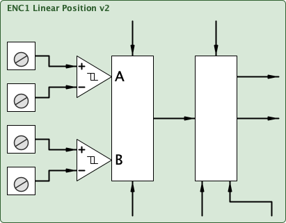 |
| Graphic with Parameters | 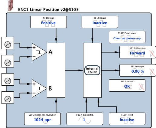 |
| Status |
Internal Parameter, Read-only, Enumerated (signed 16-bit integer) For proper operation, the Status parameter must read OK. The parameter indicates:
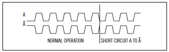
When the Status changes to a faulted state, the internal ENC# Position Block count is held at its last value until the status returns to an OK state. If a fault clears, the Status will immediately return to OK (i.e., fault conditions are not latched). For critical or sensitive applications, a drive.web connection may be made from the Status parameter to logic designed to handle a faulted encoder. Possible causes for Fault on A, Fault on B, Faults on A and B are shown below:
0 = OK 1 = Fault on A 2 = Fault on B 3 = Fault on A and B 4 = Comms Fault |
|||||||||||||||
| Pulses Per Revolution |
Input, Read-write, Analog (signed 16-bit integer) 1 ppr to 30000 ppr The Pulses Per Revolution (PPR) parameter calibrates the ENC# Position block for theattached incremental encoder. Usually, this parameter is easily determined from the model numberand is typically a power of 2 (e.g., 210 = 1024, 211 = 2048, or212 = 4096). Generally, the higher the PPR, the more precise motion profile than can beachieved. The Pulses Per Revolution (PPR) parameter is used with the Base Revs parameter toscale the Output parameter as follows: Output % = [Internal Position Count / (4 * Pulses Per Revolution * Base Revs)] * 100 |
|||||||||||||||
| Base Revs |
Input, Read-write, Analog (unsigned 16-bit integer) 1 to 65535 The Base Revs parameter calibrates the ENC# Position block for 100% output when thedesired number of revolutions is achieved. The Base Revs parameter is used with thePulses Per Revolution parameter to scale the Output parameter as follows: Output % = [64-bit Internal Position Count / (4 * Pulses Per Revolution * Base Revs)] * 100 The larger the Base Revs the lower the resolution of the Output; however, too small a Base Revs will quickly result in an overrange on the Output (i.e., either 327.67 % or - 326.67% depending on direction). Generally, it is good practice to set the Base Revs at just above the maximum expected number of revolutions and then use multiple instances of the ENC Position Monitor with the appropriate scaling for control purposes. Even if an overrange is indicated, the internal 64-bit value is maintained and updated and still available for use with other encoder count type function blocks. If the Output comes back into range, the current percentage will be displayed. |
|||||||||||||||
| Count 0 |
Internal Parameter, Read-only, Hexadecimal (unsigned 16-bit integer) 0x0 to 0xFFFF |
|||||||||||||||
| Count 1 |
Internal Parameter, Read-only, Hexadecimal (unsigned 16-bit integer) 0x0 to 0xFFFF |
|||||||||||||||
| Count 2 |
Internal Parameter, Read-only, Hexadecimal (unsigned 16-bit integer) 0x0 to 0xFFFF |
|||||||||||||||
| Count 3 |
Internal Parameter, Read-only, Hexadecimal (unsigned 16-bit integer) 0x0 to 0xFFFF |
|||||||||||||||
| Persistence |
Internal Parameter, Read-write, Boolean (signed 16-bit integer) The Persistence parameter defines the behavior of the 64-bit internal count when the moduleis powered down. By default the internal count is reset to zero at power-up. If you would like thevalue to be stored at power down, change to Persistent. 0 = Clear on power-up 1 = Persistent |
|||||||||||||||
| Sign |
Input, Read-write, Boolean (signed 16-bit integer) The Sign parameter is used in conjunction with the encoder wiring (A with respectto B channel) to determine the count direction. Behavior of the internal 64-bit count is defined below:
The Sign parameter can be controlled by logic to change the behavior of the count which directly affects the Output parameter. 0 = Positive 1 = Negative |
|||||||||||||||
| Reset |
Input, Read-write, Boolean (signed 16-bit integer) When asserted, the Reset parameter resets the 64-bit internal count to zero. 0 = Inactive 1 = Reset |
|||||||||||||||
| Output |
Output, Read-only, Analog (signed 16-bit integer) -327.67 % to 327.67 % The Output parameter is generated from the 64-bit internal count as follows: Output % = [Internal Position Count / (4 * Pulses Per Revolution * Base Revs)] * 100 If the Output exceeds +/- 327.66%, the parameter will indicate overrange; however, the 64-bit internal count is unaffected. -32767 = - overrange 32767 = + overrange |
|||||||||||||||
| Direction |
Output, Read-only, Boolean (signed 16-bit integer) The Direction parameter indicates the relationship of encoder channel A with respectto encoder channel B. To invert the behavior of the Direction parameter, swap the A and not A signals at the input terminals. |
|||||||||||||||
| Hold |
Input, Read-write, Boolean (signed 16-bit integer) When asserted, the Hold parameter prevents the count from updating. 0 = Inactive 1 = Hold |