|
Encoder
ENC1 Cyclic Position
|
| Description | This function block is used on cyclic positioning applications where there is a requirement to control movement between equally spaced locations on a fixed path. Positioning is determined using an Internal Count value accumulated from pulses on the associated encoder channel. At the end of the cycle (as determined by the Cycle Length or an external trigger), the accumulated count is reset without the loss of any encoder pulses. The following graphic shows a typical cyclic positioning scheme with important control terms highlighted: 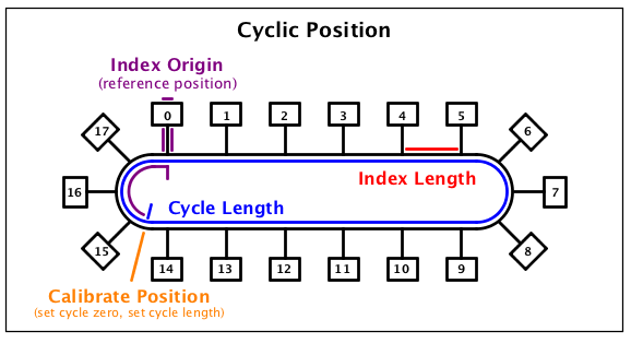 Both the Internal Count and Cycle Length are internally stored as a 64-bit numbers which increment (or decrement) with each transition of the encoder channel depending on the direction of rotation (i.e., the actual count for one revolution of the encoder will be four times the Pulses Per Revolution of the encoder). |
| Availability |
|
| savvy-SFD Graphic | 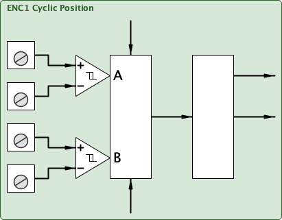 |
| Graphic with Parameters | 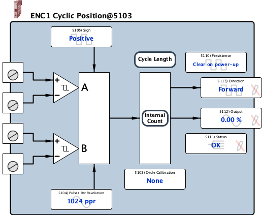 |
| Cycle Calibration |
Internal Parameter, Read-write, Optional Function Block Association (signed 16-bit integer) This parameter is used to associate a Cyclic Position function block with the appropriate Cycle Calibrator function block. If set to None, the Zero Count location must be manually set and the Cycle Length must be entered manually into the four 16-bit registers. If associated with either a Cycle Calibrator Basic or a Cycle Calibrator function block, the Internal Count zero location and the Cycle Length value can be externally manipulated making calibration and maintenance simpler while preventing long term accumulated error due to mechanical limitations. |
|||||||||||||||
| Pulses Per Revolution |
Input, Read-write, Analog (signed 16-bit integer) 1 ppr to 30000 ppr For the Cyclic Position function block, the Pulses Per Revolution (PPR) parameter is only used to calibrate an ENC Position Monitor function block. Usually, this parameter is easily determined from the encoder's model number and is typically a power of 2 (e.g., 210 = 1024, 211 = 2048, or 2 12 = 4096). Generally, the higher the PPR, the more precise motion profile that can be achieved. |
|||||||||||||||
| Sign |
Input, Read-write, Boolean (signed 16-bit integer) The Sign parameter is used in conjunction with the encoder wiring (A with respect to B channel) to determine the count direction. Behavior of the 64-bit Internal Count is defined below:
The Sign parameter can be controlled by logic to change the behavior of the count which directly affects the Output parameter. 0 = Positive 1 = Negative |
|||||||||||||||
| Count 0 |
Internal Parameter, Read-only, Hexadecimal (unsigned 16-bit integer) 0x0 to 0xFFFF Least significant 16-bits of the current 64-bit Internal Count which reflects the actual position with respect to the Cycle Zero position. Concatenate the hexadecimal values to determine the total count. For example, 0x0000 0x0BA8 0x9DE7 0x3694 = 12,818,831,586,964. |
|||||||||||||||
| Count 1 |
Internal Parameter, Read-only, Hexadecimal (unsigned 16-bit integer) 0x0 to 0xFFFF Most, least significant 16-bits of the current 64-bit Internal Count which reflects the actual position with respect to the Cycle Zero position. Concatenate the hexadecimal values to determine the total count. For example, 0x0000 0x0BA8 0x9DE7 0x3694 = 12,818,831,586,964. |
|||||||||||||||
| Count 2 |
Internal Parameter, Read-only, Hexadecimal (unsigned 16-bit integer) 0x0 to 0xFFFF Least, most significant 16-bits of the current 64-bit Internal Count which reflects the actual position with respect to the Cycle Zero position. Concatenate the hexadecimal values to determine the total count. For example, 0x0000 0x0BA8 0x9DE7 0x3694 = 12,818,831,586,964. |
|||||||||||||||
| Count 3 |
Internal Parameter, Read-only, Hexadecimal (unsigned 16-bit integer) 0x0 to 0xFFFF Most significant 16-bits of the current 64-bit Internal Count which reflects the actual position with respect to the Cycle Zero position. Concatenate the hexadecimal values to determine the total count. For example, 0x0000 0x0BA8 0x9DE7 0x3694 = 12,818,831,586,964. |
|||||||||||||||
| Persistence |
Internal Parameter, Read-write, Boolean (signed 16-bit integer) The Persistence parameter defines the behavior of the 64-bit Internal Count when the module is powered down. By default the Internal Count is reset to set to Clear on power-up. If you would like the value to be stored at power down, change to Persistent. 0 = Clear on power-up 1 = Persistent |
|||||||||||||||
| Status |
Internal Parameter, Read-only, Enumerated (signed 16-bit integer) For proper operation, the Status parameter must read OK. The parameter indicates:
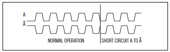
When the Status changes to a faulted state, the Internal Count is held at its last value until the Status returns to an OK state. If the fault clears, the Status will immediately return to OK (i.e., fault conditions are NOT latched). For critical or sensitive applications, a drive.web connection may be made from the Status parameter to logic designed to handle a faulted encoder. Possible causes for Fault on A, Fault on B Faults on A and B are shown below:
If the Status parameter indicates a Comms Fault, there may be extreme radio frequency (RF) noise coupling to your smarty2 I2I signal wires, a wiring fault, or a hardware fault. Check for proper shielding and routing of cabling. 0 = OK 1 = Fault on A 2 = Fault on B 3 = Fault on A and B 4 = Comms Fault |
|||||||||||||||
| Output |
Output, Read-only, Analog (signed 16-bit integer) 0.00 % to 100.00 % The Output parameter is generated from the 64-bit Internal Count as follows: |
|||||||||||||||
| Direction |
Output, Read-only, Boolean (signed 16-bit integer) The Direction parameter indicates the relationship of encoder channel A with respect to encoder channel B. To invert the behavior of the Direction parameter, swap channel A and -A at the input terminals. 0 = Forward 1 = Reverse |
|||||||||||||||
| Cycle Length 0 |
Internal Parameter, Read-write, Hexadecimal (unsigned 16-bit integer) 0x0 to 0xFFFF Least significant 16-bits of the 64-bit Cycle Length. Concatenate the hexadecimal values to determine the total length. For example, 0x0000 0x0BA8 0x9DE7 0x3694 = 12,818,831,586,964. |
|||||||||||||||
| Cycle Length 1 |
Internal Parameter, Read-write, Hexadecimal (unsigned 16-bit integer) 0x0 to 0xFFFF Most, least significant 16-bits of the 64-bit Cycle Length. Concatenate the hexadecimal values to determine the total Length. For example, 0x0000 0x0BA8 0x9DE7 0x3694 = 12,818,831,586,964. |
|||||||||||||||
| Cycle Length 2 |
Internal Parameter, Read-write, Hexadecimal (unsigned 16-bit integer) 0x0 to 0xFFFF Least, most significant 16-bits of the 64-bit Cycle Length. Concatenate the hexadecimal values to determine the total Cycle Length. For example, 0x0000 0x0BA8 0x9DE7 0x3694 = 12,818,831,586,964. |
|||||||||||||||
| Cycle Length 3 |
Internal Parameter, Read-write, Hexadecimal (unsigned 16-bit integer) 0x0 to 0xFFFF Most significant 16-bits of the 64-bit Cycle Length. Concatenate the hexadecimal values to determine the total Cycle Length. For example, 0x0000 0x0BA8 0x9DE7 0x3694 = 12,818,831,586,964. |