| Enable |
Input, Read-write, Boolean (signed 16-bit integer)
All outputs are immediately disabled when this parameter is inactive.
0 = Inactive
1 = Enable
|
| M-Start 1 |
Input, Read-write, Boolean (signed 16-bit integer)
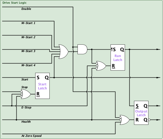
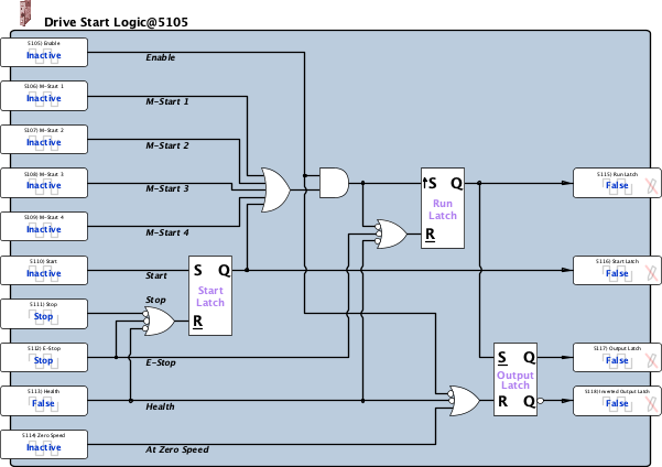
Typical multi-section machine startup and stopping sequence; - The enable signal is activated to indicate that the machine is ready to run.
A maintained-start is initiated and the local section is commanded to run and the drive output is enabled. This step may be optional depending on the starting-requirements of the section. The start signal is given and the drive starts to rotate the motor. The start latch output may be used directly to control a PLX or P2 drive's maintained-start command input. At the end of production the stop command is given and the local run and start command outputs are disabled. The drive continues to control motor rotation until zero-speed is indicated and the drive output command is disabled. For example, the output latch may be used to control a PLX drive's Run or Coast command inputs or a P2 drive's STO, safe torque-off, circuit.
Unusual stopping conditions; The enable signal is disabled and all command outputs are immediately disabled. E-Stop is activated. This is similar to a normal, motor-drive controlled-stop although a faster decel ramp may be selected separately. The health signal is disabled and all command outputs are immediately disabled.
Where separate run and start outputs are not required, the maintained-starts can be used to start and stop the drive via the run output.
0 = Inactive
1 = Start
|
| M-Start 2 |
Input, Read-write, Boolean (signed 16-bit integer)
Typical multi-section machine startup and stopping sequence; - The enable signal is activated to indicate that the machine is ready to run.
A maintained-start is initiated and the local section is commanded to run and the drive output is enabled. This step may be optional depending on the starting-requirements of the section. The start signal is given and the drive starts to rotate the motor. The start latch output may be used directly to control a PLX or P2 drive's maintained-start command input. At the end of production the stop command is given and the local run and start command outputs are disabled. The drive continues to control motor rotation until zero-speed is indicated and the drive output command is disabled. For example, the output latch may be used to control a PLX drive's Run or Coast command inputs or a P2 drive's STO, safe torque-off, circuit.
Unusual stopping conditions; The enable signal is disabled and all command outputs are immediately disabled. E-Stop is activated. This is similar to a normal, motor-drive controlled-stop although a faster decel ramp may be selected separately. The health signal is disabled and all command outputs are immediately disabled.
Where separate run and start outputs are not required, the maintained-starts can be used to start and stop the drive via the run output.
0 = Inactive
1 = Start
|
| M-Start 3 |
Input, Read-write, Boolean (signed 16-bit integer)
Typical multi-section machine startup and stopping sequence; - The enable signal is activated to indicate that the machine is ready to run.
A maintained-start is initiated and the local section is commanded to run and the drive output is enabled. This step may be optional depending on the starting-requirements of the section. The start signal is given and the drive starts to rotate the motor. The start latch output may be used directly to control a PLX or P2 drive's maintained-start command input. At the end of production the stop command is given and the local run and start command outputs are disabled. The drive continues to control motor rotation until zero-speed is indicated and the drive output command is disabled. For example, the output latch may be used to control a PLX drive's Run or Coast command inputs or a P2 drive's STO, safe torque-off, circuit.
Unusual stopping conditions; The enable signal is disabled and all command outputs are immediately disabled. E-Stop is activated. This is similar to a normal, motor-drive controlled-stop although a faster decel ramp may be selected separately. The health signal is disabled and all command outputs are immediately disabled.
Where separate run and start outputs are not required, the maintained-starts can be used to start and stop the drive via the run output.
0 = Inactive
1 = Start
|
| M-Start 4 |
Input, Read-write, Boolean (signed 16-bit integer)
Typical multi-section machine startup and stopping sequence; - The enable signal is activated to indicate that the machine is ready to run.
A maintained-start is initiated and the local section is commanded to run and the drive output is enabled. This step may be optional depending on the starting-requirements of the section. The start signal is given and the drive starts to rotate the motor. The start latch output may be used directly to control a PLX or P2 drive's maintained-start command input. At the end of production the stop command is given and the local run and start command outputs are disabled. The drive continues to control motor rotation until zero-speed is indicated and the drive output command is disabled. For example, the output latch may be used to control a PLX drive's Run or Coast command inputs or a P2 drive's STO, safe torque-off, circuit.
Unusual stopping conditions; The enable signal is disabled and all command outputs are immediately disabled. E-Stop is activated. This is similar to a normal, motor-drive controlled-stop although a faster decel ramp may be selected separately. The health signal is disabled and all command outputs are immediately disabled.
Where separate run and start outputs are not required, the maintained-starts can be used to start and stop the drive via the run output.
0 = Inactive
1 = Start
|
| Start |
Input, Read-write, Boolean (signed 16-bit integer)
Typical multi-section machine startup and stopping sequence; - The enable signal is activated to indicate that the machine is ready to run.
A maintained-start is initiated and the local section is commanded to run and the drive output is enabled. This step may be optional depending on the starting-requirements of the section. The start signal is given and the drive starts to rotate the motor. At the end of production the stop command is given and the local run and start command outputs are disabled. The drive continues to control motor rotation until zero-speed is indicated and the drive output command is disabled.
Unusual stopping conditions; The enable signal is disabled and all command outputs are immediately disabled. E-Stop is activated. This is similar to a normal, motor-drive controlled-stop although a faster decel ramp may be selected separately. The health signal is disabled and all command outputs are immediately disabled.
Typical multi-section machine startup and stopping sequence; - The enable signal is activated to indicate that the machine is ready to run.
A maintained-start is initiated and the local section is commanded to run and the drive output is enabled. This step may be optional depending on the starting-requirements of the section. The start signal is given and the drive starts to rotate the motor. The start latch output may be used directly to control a PLX or P2 drive's maintained-start command input. At the end of production the stop command is given and the local run and start command outputs are disabled. The drive continues to control motor rotation until zero-speed is indicated and the drive output command is disabled. For example, the output latch may be used to control a PLX drive's Run or Coast command inputs or a P2 drive's STO, safe torque-off, circuit.
Unusual stopping conditions; The enable signal is disabled and all command outputs are immediately disabled. E-Stop is activated. This is similar to a normal, motor-drive controlled-stop although a faster decel ramp may be selected separately. The health signal is disabled and all command outputs are immediately disabled.
0 = Inactive
1 = Start
|
| Stop |
Input, Read-write, Boolean (signed 16-bit integer)
Typical multi-section machine startup and stopping sequence; - The enable signal is activated to indicate that the machine is ready to run.
A maintained-start is initiated and the local section is commanded to run and the drive output is enabled. This step may be optional depending on the starting-requirements of the section. The start signal is given and the drive starts to rotate the motor. The start latch output may be used directly to control a PLX or P2 drive's maintained-start command input. At the end of production the stop command is given and the local run and start command outputs are disabled. The drive continues to control motor rotation until zero-speed is indicated and the drive output command is disabled. For example, the output latch may be used to control a PLX drive's Run or Coast command inputs or a P2 drive's STO, safe torque-off, circuit.
Unusual stopping conditions; The enable signal is disabled and all command outputs are immediately disabled. E-Stop is activated. This is similar to a normal, motor-drive controlled-stop although a faster decel ramp may be selected separately. The health signal is disabled and all command outputs are immediately disabled.
0 = Stop
1 = Inactive
|
| E-Stop |
Input, Read-write, Boolean (signed 16-bit integer)
E-Stop is similar to a normal, motor-drive controlled-stop although a faster decel ramp may be selected separately. The output is active until zero speed is indicated
0 = Stop
1 = Inactive
|
| Health |
Input, Read-write, Boolean (signed 16-bit integer)
All outputs are immediately disabled when this parameter is inactive.
0 = False
1 = True
|
| Zero Speed |
Input, Read-write, Boolean (signed 16-bit integer)
Zero speed signal is required to de-latch the output after a normal, motor-drive controlled-stop.
0 = Inactive
1 = Zero Speed
|
| Run Latch |
Output, Read-only, Set to default on hard initialization, Boolean (signed 16-bit integer)
Used as a local section enable signal. Also may be used as a drive start signal when only maintained-start signals are used.
0 = False
1 = True
|
| Start Latch |
Output, Read-only, Set to default on hard initialization, Boolean (signed 16-bit integer)
Used as a drive start signal in conjunction with the start and stop input signals. This may be used directly to control a PLX or P2 drive's maintained-start command input.
0 = False
1 = True
|
| Output Latch |
Output, Read-only, Set to default on hard initialization, Boolean (signed 16-bit integer)
The output latch may be used to control the drive's output, e.g., a PLX drive's Run or Coast command inputs or a P2 drive's STO, safe torque-off, circuit.
0 = False
1 = True
|
| Inverted Output Latch |
Output, Read-only, Set to default on hard initialization, Boolean (signed 16-bit integer)
0 = False
1 = True
|