
General
The ENC Speed Lock function block accepts two quadrature encoder inputs and provides an error output that is an absolute measure of the difference in speed between the encoders. This error output can be adjusted (via the ratio and scaler parameters) to account for differences in encoder PPR (pulses per revolution) as well as gear ratios in the machine.

Details
Each encoder input has a counter that counts the number of input transitions it receives (there are four transitions per pulse, so a 1024 PPR encoder will see 4096 transitions in a revolution). The number of counts accumulated in a timebase period is used to calculate the output. For example, a 1024 PPR encoder running at 3000 RPM with a 50 ms timebase period would accumulate 4 * 1024 * (3000/60) * (50/1000) = 10240 counts.
Each encoder input has an associated ratio parameter. The counts are multiplied by their ratio, and the difference between them is then divided by the scaler parameter to produce the error output. The internal calculation has 32-bit resolution, but the error output is limited to 16-bit resolution. For some systems, these resolution limitations are significant and this is discussed below.
Speed Lock
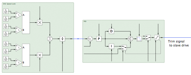
A common application is to have a "slave" drive follow a "master" drive in "speed lock". In this case, the error output is connected to a PID (with a zero setpoint) and the output of the PID is then used to trim the speed setpoint to the slave drive.
Phase Lock
Another common application is to have a "slave" drive follow a "master" drive in "phase lock". In this case, the error output is connected to an integrator (which produces a phase error). The integrator output is then connected to a PID (with a zero setpoint) and the output of the PID is used to trim the speed setpoint to the slave drive. A summing junction can be placed before the integrator to allow the relative phase to be adjusted.

Gear Ratios
If the encoders have different PPR's or if there are gears or belts involved, or both, then this must be accounted for.
The first step is to decide on the appropriate ratio parameters - determine how many counts one encoder will produce with respect to the other encoder, then pick ratios that make the numbers at the summing junction equal.
For example, if encoder 1 is 1024 PPR, encoder 2 is 1500 PPR, encoder 1 has a 3.4:1 gear ratio, and encoder 2 has a 6.5:1 gear ratio:
encoder 1 pulses per unit = 1024 / 3.4
encoder 2 pulses per unit = 1500 / 6.5
In order to make the numbers at the summing junction equal, we need to multiply each channel by the number of pulses per unit of the other channel:
encoder 1 ratio = 1500 / 6.5
encoder 2 ratio = 1024 / 3.4
we then rationalize the numbers:
encoder 1 ratio = 1500 * 3.4 = 5100
encoder 2 ratio = 1024 * 6.5 = 6656
and remove any common factors (in this case 4):
encoder 1 ratio = 5100 / 4 = 1275
encoder 2 ratio = 6656 / 4 = 1664
A check should be done to ensure that the 32-bit internal values will not overflow (±2,147,483,647).
For 1000 units/minute and a 50 ms timebase:
encoder 1: 4 * (1024 / 3.4) * (1000/60) * (50/1000) * 1275 = 1,280,000 counts per timebase
encoder 2: 4 * (1500 / 6.5) * (1000/60) * (50/1000) * 1664 = 1,280,000 counts per timebase
1,280,000 is less than the limit of 2,147,483,647, so this is OK. (The counts per timebase should always be equal if the earlier calculations are correct.)
The final step is to determine if the resulting error needs to be scaled. This is a function of the machine dynamics, the drive performance, and the control loop performance. Scaling will introduce truncation errors, but it may occasionally be necessary to avoid overflowing the 16-bit error output (±32,767) - values that would overflow are clamped to ±32,767.
Note that changing the ratios and scaler directly affects the control loop gain and will usually require the PID to be re-tuned.