
General
The dw Option -25 EIP PCCC Server enables your second generation drive.web product (dw2xx ) to communicate with EIP PCCC Clients which support the EtherNet/IP PCCC (Programmable Controller Communication Commands). The dw2xx product emulates a PLC5 Allen-Bradley processor using PCCC communications.
Server Configuration
There is no special programming required in the dw2xx savvy configuration to support the EIP PCCC Server. The only requirement is the dw Option -25 be enabled. To determine if you drive.web product has the EIP PCCC Server enabled, perform a Get Detailed Info on the device.
 |
 |
Client Configuration
In order to communicate with the dw2xx device, you will need to map PLC5 file/register information to parameter ID numbers in the drive.web device. Generally, the following information will be required to configure the Client.
- Supported Commands
- PLC5 Typed Read, PLC5 Typed Write
- Supported PLC5 File Numbers
- N10, N11, N12, N13, N26, N27, N28, N29
- Supported Registers Addresses
- 0 through 255
- Connections Supported
- Up to 2 simultaneous connections
Design Considerations
The EtherNet/IP PCCC Server allows the user to directly connect to any supported Parameter ID Number (PIN) within a dw2xx configuration; however, individually accessing parameters at various locations in a configuration is a very inefficient method for transferring data. Whether accessing 1 or 100 parameters, the same EIP PCCC overhead data (i.e, header & addressing information) is required for each individual EIP PCCC message.
Communication link performance can be greatly improved, and programming of the Client's EIP PCCC messages made much simpler, by transferring data to/from contiguous PIN's (i.e., the parameter addresses are sequential with no skips). Normally, savvy automatically assigns PIN's as you drop function blocks into your configuration. The allocated addresses are based on the number of parameters associated with the placed function block and inherently contiguous. In order to access the parameters of interest for your control scheme, you would typically need to jump around in your configuration to a myriad of PIN's scattered throughout your design (i.e., the PIN's are NOT contiguous).
With a bit of planning, generating contiguous PIN's is fairly simple. If you determine in advance the number of parameters to be transferred via EIP PCCC messaging, you can drop certain function blocks that may be connected to any parameters distributed throughout your design while keeping the PIN's accessed by the EIP PCCC comms link contiguous.
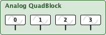
Analog Parameter Block
The Analog Parameter Block is useful in mapping parameters which would normally be distributed throughout a configuration, at various addresses, into contiguous memory. The block is in the Utility category of the System & I/O Library group of all dw2xx devices. Each function block has four parameters with contiguous Parameter ID Numbers (PIN's).
Using this function block serves two purposes:
- It keeps the PIN's contiguous making large data transfers possible.
- It makes outside connections into your design more intuitive and easier to follow.
Manual Addressing
If you manually assign the addresses before doing any other design work in the dw2xx configuration, you can choose the desired address space without the possibility of overlapping function blocks' address space. The following example describes the process.
If you look up the Parameter ID numbers associated with PLC-5 File 26 in the EIP PCCC Mapping you can see N26:0 through N26:3 maps to PIN's 4096 through 4099. To manually assign addresses, right-click on any white space in your savvy-SFD drawing and select the Add Function Block... menu item.
 |
 |
Then, un-check the Automatic box and type in the desired starting address of 4096. Repeat this process with starting addresses of 4100, 4104, and 4108 and there will be 16 contiguous registers in the PLC-5 address space from N26:0 through N26:15 which can be addressed with one EtherNet/IP PCCC message.
Automatic Addressing
You can use the Automatic addressing feature of savvy to assign contiguous addresses by dropping each Analog Parameter Block one right after another. However, when using the Automatic method, the PIN numbers could be anywhere in the dw2xx configuration's available address space (based on your configuration). Notice, as you drop the blocks, the starting PIN numbers for each block are four less than the previous block's starting PIN number with each subsequent block placed (i.e., addresses are assigned from last possible, downward).
Be aware savvy's Automatic mode intelligently scans through available memory looking for the first available slot in which a function block will fit. If during your design you have deleted function blocks, the memory space could be fragmented resulting in your blocks not being contiguous even though the blocks were created one right after another. After dropping the function blocks, check the PIN numbers to ensure the PIN's are indeed contiguous. If not, continue to create blocks until you have created enough blocks so they are in contiguous address space.
Once the PIN numbers are contiguous, use the EIP PCCC Mapping to look up the appropriate EIP PCCC file and register numbers to use in the Client's message transfer setup.
Boolean Data
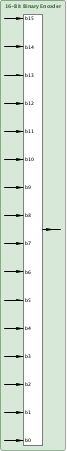
For boolean data (e.g., digital inputs/outputs), there are two function blocks that may be used to pack status/control bits into one 16-bit word of data. By encoding/ decoding the 16-bits, the traffic on the wire can be minimized improving the overall perfomance of the communication link. The 16-Bit Binary Encoder and 16-Bit Binary Decoder are included in the Logic category of the Process Control Library (dwOption -05) group as shown below:
| Encoder | Decoder | |
|---|---|---|
 |
 |
The output of the encoder block and the input to the decoder block may then be connected to an Analog Parameter Block so the entire 16 status/control bits are transferred as one word of data. Again, minimizing the traffic on-the-wire and optimizing comms link performance.
Programming Examples
When programming Allen-Bradley processors, MSG (Message) blocks are used to move the data from local processor memory, across Ethernet using the EIP PCCC protocol, and into the appropriate associated drive.web parameters. Mapping of drive.web parameters to PLC5 type file numbers/registers is fixed and defined by the appropriate EIP PCCC Addressing mapping document.
drive.web Configuration
For the following sample PLC programs, a simple loopback program in the smarty2 will suffice. In this program, eight 16-bit words are written & read from the dw210 at IP address 192.168.1.71. The incoming data (PLC Writes) are directly connected to the outgoing data (PLC Reads) via drive.web connections. So, the incoming information is effectively echoed back to the Client PLC.
Incoming Data from the PLC
The PLC writes to two Analog Parameter Blocks with contiguous parameter ID's 4352 through 4359.
Looking at the EIP PCCC mapping for these parameters the drive.web parameters are addressed using PLC File 27, Registers 0 through 7 (N27:000 through N27:007).
Outgoing Data to PLC
The PLC reads from two Analog Parameter Blocks with contiguous parameter ID's 4864 through 4871.
Looking at the EIP PCCC mapping for these parameters the drive.web parameters are addressed using PLC File 29, Registers 0 through 7 (N29:000 through N29:007).
Sample drive.web Configuration Summary
The following table summarizes the EIP PCCC mapping used in the programming example.
| PLC Write | Incoming PIN | Outgoing PIN | PLC Read | |||
|---|---|---|---|---|---|---|
| N27:0 | => | 4352 | => | 4864 | => | N29:0 |
| N27:1 | => | 4353 | => | 4865 | => | N29:1 |
| N27:2 | => | 4354 | => | 4866 | => | N29:2 |
| N27:3 | => | 4355 | => | 4867 | => | N29:3 |
| N27:4 | => | 4356 | => | 4868 | => | N29:4 |
| N27:5 | => | 4357 | => | 4869 | => | N29:5 |
| N27:6 | => | 4358 | => | 4870 | => | N29:6 |
| N27:7 | => | 4359 | => | 4871 | => | N29:7 |
PLC Programming Examples
To transfer data to/from the drive.web configuration described above, detailed programming examples for the following Allen-Bradley PLC platforms follow: