General
The Allen-Bradley MicroLogix PLC uses MSG function blocks to create the Client interface for initiating the EIP PCCC transfers. For Write messages, the MSG function block specifies the source location of the data to be sent to the appropriate dw210 addresses. For Read messages, the MSG function block specifies the destination for the data when a range of dw210 addresses is queried.
For the following PLC programming example, the previously described drive.web Configuration with eight contiguous parameters mapping to PLC addresses N27:0-7 (Writes) and N29:0-7 (Reads) is used.
For the MicroLogix PLC, two MSG blocks must be instantiated in the program. One for writing the data to the dw210 and another for reading the data. There will be a different Message Control block for the read and the write transfers of data.
Write MSG Block
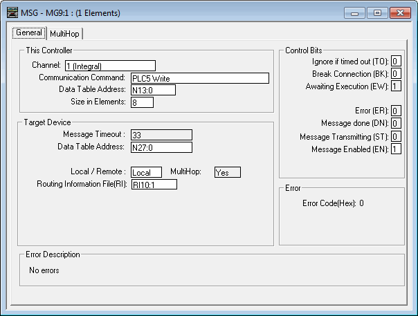
The Write MSG block's configuration information is stored in Message File MG9:1 as shown below:

Setup Screen
Clicking on Setup Screen text of the MSG Function Block will open the a configuration window. Select the General configuration tab.
General Tab
Refers to the MSG function block's interaction with the local MicroLogix processor.

This Controller Section
| Channel: | 1 (Integral) | Accesses the local Ethernet port. |
| Communication Command: | PLC5 Write | Type of EIP PCCC command. |
| Data Table Address: | N13:0 | Local PLC starting address of the write data. |
| Size in Elements: | 8 | Number of 16-bit parameters to write. |
Target Device Section
Refers to the MSG function block's interaction with the remote EIP PCCC Server. In this case, a dw210 with the EIP PCCC Server option dwOption -24.
| Message Timeout: | 33 | Wait time for response before error (seconds). |
| Data Table Address: | N27:0 | Starting address in the dw210 of the write data. |
| Local/Remote | Local | The data will NOT be transmitted through a bridge. |
| MultiHop: | Yes | Routing information, see MultiHop tab. |
| Routing Information File(RI): | RI10:1 | Local file where all the MSG configuration info is stored. |
MultiHop Tab
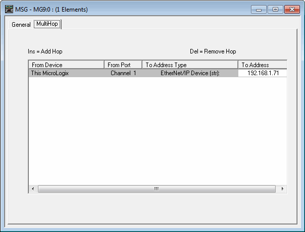
The MultiHop tab is used to set the destination address of the EIP PCCC Server, in this case, a dw210.

| To Address: | 192.168.1.71 | IP address of the dw210. |
Read MSG Block
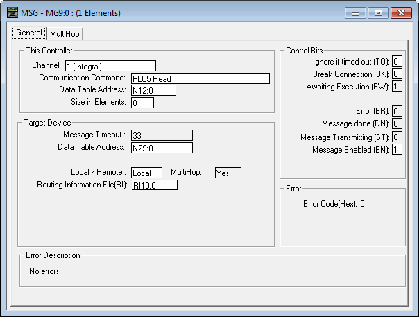
The Write MSG block's configuration information is stored in Message File MG9:0 as shown below:

General Tab
Clicking on Setup Screen text of the MSG Function Block will open the General configuration tab.

This Controller Section
Refers to the MSG function block's interaction with the local MicroLogix processor.
| Channel: | 1 (Integral) | Accesses the local Ethernet port. |
| Communication Command: | PLC5 Read | Type of EIP PCCC command. |
| Data Table Address: | N12:0 | Local PLC starting address of the read data. |
| Size in Elements: | 8 | Number of 16-bit parameters to read. |
Target Device
Refers to the MSG function block's interaction with the remote EIP PCCC Server. In this case, a dw210 with the EIP PCCC Server option dwOption -24.
| Message Timeout: | 33 | Wait time for response before error (seconds). |
| Data Table Address: | N29:0 | Starting address in the dw210 of the write data. |
| Local/Remote | Local | The data will NOT be transmitted through a bridge. |
| MultiHop: | Yes | Routing information, see MultiHop tab. |
| Routing Information File(RI): | RI10:0 | Local file where all the MSG configuration info is stored. |
MultiHop Tab
The MultiHop Tab is used to set the destination address of the EIP PCCC Server, in this case, a dw210.

| To Address: | 192.168.1.71 | IP address of the dw210. |
Sample Program
The preceding sections only cover the basic MSG block's configuration. A sample program with detailed triggering, error recovery, and comms link performance indicators are included in a complete sample MicroLogix program available at driveweb.com. A savvy-ready complementary loopback dw210 configuration is included in this download.
Click here to download the sample program.
